A survey company changes its tactics to monitor an auditorium roof before, during, and after its lift into place, using teamwork and true professionalism.
American Surveying & Engineering, P.C. (with corporate headquarters in Chicago, Illinois) was approached by JP Cullen (a contractor with headquarters in Janesville, Wisconsin) with a challenging project: a particularly tricky auditorium in need of a roof.
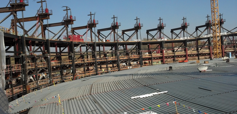
Located in Verona, Wisconsin, this auditorium has approximately 110,000 square feet clear span. The roof is a semi-circular section with a 280-foot radius and 130 degree arc, built with 18 radial girders that created 17 bays going from just a few feet to 45 feet in width. Once built, the structure would be covered with concrete, soil, and vegetation to blend into the natural setting of the site.
JP Cullen analyzed the cost of building the roof in place above the floor of the auditorium versus the cost of building the roof at grade and raising it approximately 45 feet to its final position. They decided it would be more cost-effective to build the roof on grade and avoid the use of man lifts for nearly every operation during construction, despite the construction, despite the cost to raise it afterwards.
The challenge was how to raise the 8.7-million-pound roof into place on the support structure. The solution was to use strand jacks set above the final roof level to lift the roof up and bolt it into the support structure.
To ensure that the structure maintained the proper shape and structural integrity during the lifting operation, American Surveying & Engineering (ASE) was brought on board to provide surveying of the structure before, during, and after the lift.
JP Cullen, a progressive construction company, was familiar with 3D terrestrial lidar and was interested in using the technology to monitor the structure while under construction and during the lift. Based on the initial estimate of 76 points of interest, ASE began working up a project approach, schedule, and cost for submission to JP Cullen, the owner (Epic), and the structural engineer (Thornton Tomasetti, Inc.). However, it was not long until the team realized this approach would not work.
As the plans were analyzed and discussions regarding the location of the points of interest opened, the number of points grew. Each girder contained at least three areas of interest, one at each end and one in the middle. In most cases, there was a point near the bottom of the girder and a second one nearly 20 feet higher on the top of the girder, creating a total of six points per girder. With points of interest on the support structure and other various locations, the count grew to approximately 230 total points.
Plan of Many Scans
The original project approach called for a scan to be performed from every second bay, yielding nine or ten total set-ups. The points of interest would be modeled with a coordinate produced for each. An example of the modeled point is shown in the screen capture above. Shortly after opening discussions with the team, it soon became apparent the time required for the setups, registration, modeling, and reporting would be much too slow and would not work with the overall project schedule.
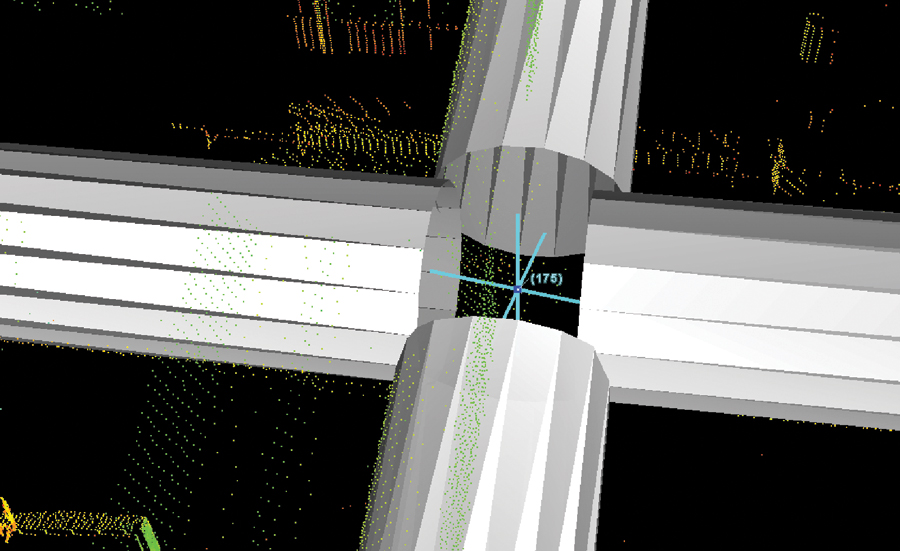
The original plan called for a point to be created using lidar scans, with modeling as shown above.
The structural engineer was interested in monitoring the points at five different stages of construction. The first observation would provide the baseline for the location of the target points relative to the steel girders while at rest on concrete pedestals. The second observation would be taken once the roof was lifted approximately two feet.
Once compared to the baseline location, this report would provide the first indication of how the structure was reacting (stretching, bending, and moving) to the lift. The structural engineer would compare the actual reaction to the anticipated one; if the reaction was within expected parameters, the structural engineer would approve the remainder of the 45-foot lift.
The third observation would be made at the time the roof structure was completely connected to the columns of the supporting structure. This observation would become the new baseline for monitoring the locations during loading of concrete and soil cover on the roof.
The largest time constraint would be between the 2-foot lift and the final 45-foot lift. To meet the lift schedule, the general contractor could give no more than four hours from when the initial two-foot lift was complete and when the final reported position was provided to the structural engineer.
Ignoring the set-up, downloading, registration, and reporting time, the four hours allotted would require modeling each point of interest in just over one minute each. That alone made this project approach nearly impossible, but once it was determined the roof would be covered with steel and the girders would be full of various building appurtenances, the plan was scrapped altogether.
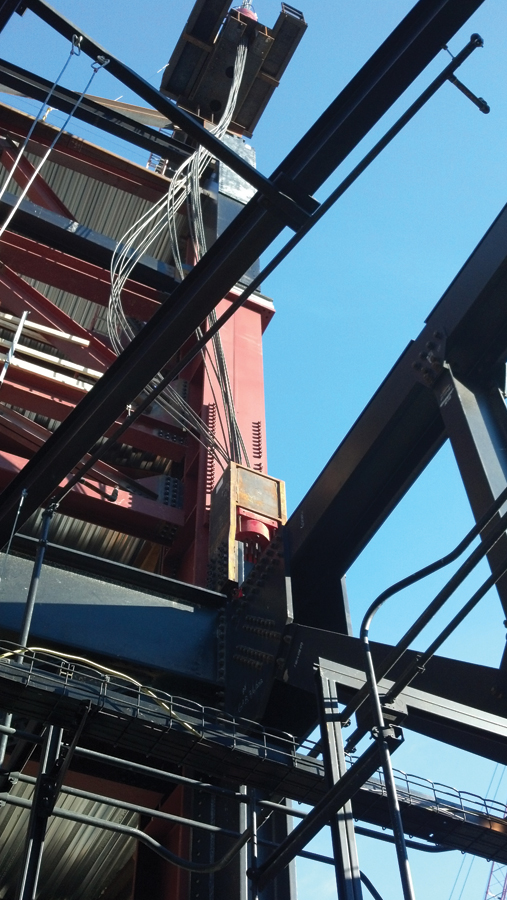
Lifting the roof into its final position was the job of the strand jacks, using multiple lines of steel cable attached to the roof.
At the initial onsite meeting, the team walked away with a new understanding and vision of the challenge. Standing near the center of the bay looking out, it seemed almost claustrophobia-inducing. The girders were over 20 feet high and contained most of the final wiring, plumbing, heating, ventilation, air conditioning, and catwalks that would be used later by production and lighting crews. To see all the points, at least 15 different setup locations and probably twice that number would be required.
At this point, most project managers reading this start to get uneasy and hear bells and whistles going off, warning of scope creep and budget arguments found in the typical contractor and sub-contractor relationship. If that is the case with you, relax and keep reading.
Plan of Specific Targets
The approach that we ultimately accepted required the use of specific targets installed near the points of interest on a planned offset. The project had been modeled in Navisworks and included most of the major building appurtenances.
Using this model, JP Cullen placed a target at a specific offset to the point of interest; the points were then reviewed and approved by the structural engineer. Working backward from the targets, a line of sight was drawn to proposed set-up locations and then checked for interference. An effort was made to maximize the number of targets located per set-up to reduce the number of required set-ups. A spreadsheet was created to keep track of the number of set-ups and number of targets to be located from each set-up.
Using a very conservative estimate of half an hour per set-up and five minutes per target location, we estimated that up to 12 instruments and operators would be required to meet the time schedule. This number was used anticipating potential problems with equipment, personnel, and line-of-sight issues with objects that were not modeled.
Then we made a plan for in-house and rental equipment that included the use of three instruments and operators from two different companies (Sanchez & Associates and Morris).
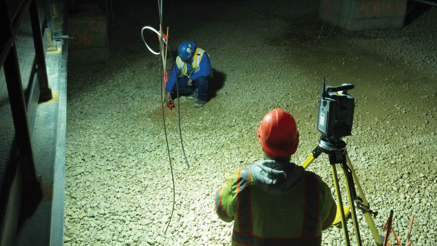
In an effort to reduce the time acquiring targets and given the fact that a number of the targets would be impossible to observe through the instruments due to the vertical angle, we decided to use small glass prisms that would allow the gun to auto-lock on the center of the target. Plan target coordinates from the model were uploaded to the data collectors and used to “stake out” the points, thereby getting the instruments close enough to auto-lock on the prisms.
The First Observation (Baseline)
Line of sight was greatly reduced by the catwalks used to support lighting and stage activities for the final auditorium; anticipating the effect of the two-foot lift would have was an enormous challenge.
Our surveyors established control, staked out the planned set-up points, and installed and aligned the prisms towards the appropriate set-up point. Prior to the first observations, a series of baselines were established on site and used to confirm that each instrument used on the project was calibrated and matched to one another.
During the first observation, numerous issues were corrected, changed, and/or recorded for the next observation during the two-foot lift, including line-of-sight obstructions, prism alignment, prisms installed at the wrong location, and site conditions at the set-up point differing from plan (elevations that changed the height of instrument).
Observation points were uploaded into a spreadsheet to check that each point observed was correctly identified and that all points were accounted for in the files. In numerous cases the line of sight for one prism was too close to a second prism, resulting in the wrong prism being observed.
The first observation (actually a series) was performed over the course of several days. The first sets of observations indicated that a corrective shift was required in portions of the steel, thereby rendering the first observations obsolete. After the corrective shift, two more sets of observations were taken, the first as the baseline and the second as a check to confirm the repeatability of the observations.
The Two-foot Lift
The night before the big lift, ASE mobilized 12 surveyors, including two staff members from Sanchez & Associates for a pre-lift meeting who reviewed the safety protocol and revisions to the observation plan that were recorded from the first observation. Some of the set-ups had been removed completely, some were added, and some had as many as four changes to the height of instrument required to see 100% of the targets.
Each set-up had its own sheet used to confirm that all targets were observed from the various elevations of each set-up. Sighting a combination of prism stickers, several different types of prisms used on control, and the mini prisms used for target points with varying offsets required that each observation include a check to make sure the prism constant had been changed on the data collector.
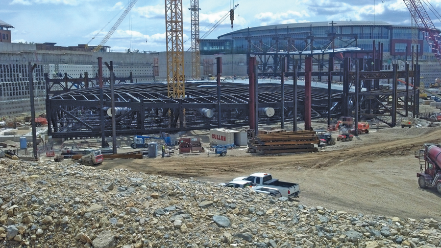
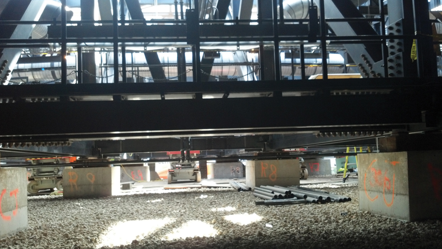
Built nearly 100 feet below the final grade, the auditorium awaits its burial.
On the morning of the lift, JP Cullen instituted a strict isolation policy for the project site; access was restricted to only those who were deemed to have a need to be on site and who had gone through the site safety briefing.
ASE was met on-site by the Morris surveyors who had been some of the project site layout surveyors from the beginning of the project. They provided two surveyors and four instruments, two of which were backups in case equipment problems were encountered. During the baseline observations, set-ups were divided into those under the roof and those outside of the roof. Morris was assigned the set-ups outside, and ASE performed the work under the roof.
While waiting for the two-foot lift to take place, all instruments were run through the baselines to confirm the calibration of each instrument. After the two-foot lift was made and all safety procedures and tie offs were made, ASE was allowed under the now-hanging 8.7-million-pound roof.
Despite all the preparation, documentation, and changes made to the set-ups during the first observation, a quarter of the set-ups had to be revised to accommodate the changes to the line of sight with the lift, and several new set-ups had to be made to observe one or two points each. Even with the last-minute changes, the team of 14 surveyors made the 230 observations in approximately two and a half hours.
Short back sights and the lack of stabile monuments presented a challenge to accuracy.
Success
Based on the results of the two-foot lift, the structural engineer determined that the steel girders were reacting as anticipated and the remaining lift could proceed.
The roof was raised over the next day and placed in the final position so the iron workers could make the connections to the supporting structure. Although the final back filling and covering took months to complete and required several additional surveys to monitor the loading of the roof, ASE considered the project nearly over, and a success.
Especially noteworthy in the overall teamwork was JP Cullen, who at every step of the project created an environment of safety and teamwork. Everyone went into this project with a “win-win” instead of an “I win – you lose” attitude, which allowed for creativity and sharing of work, knowledge, and reward, which meant success rather than failure.
One of the simplest, although not complete, definitions for “professionalism” could be practicing a win-win attitude. Today, the term “professionalism” suffers an identity crisis from over-use in media and advertising; other similarly elusive terms have failed a strict definition. However, as Supreme Court Justice Potter Stewart once said, “I know it when I see it.” On this project, I saw professionalism from every team member and felt grateful to be a part of it.
The project “Deep Space” was selected for an AGC Build America Award for 2014, then the Grand Award (or best of the best) for the nation in 2014.