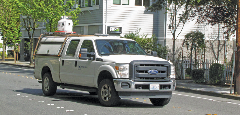
A surveyor examines (and asks users a lot of questions about) the Pegasus:Two system.
Editor’s note: How could measurements taken from a moving vehicle possibly yield surety in high precision and accuracy? These are questions we hear from surveyors and geospatial professionals, surveyors in particular as masters of professional determinations of boundary and other spatial elements that require assurance. The measurement aspect of such determinations have traditionally involved exacting, fixed, and often discrete positions. But how to consider a sophisticated device, spraying a million laser shots per second, gathering thousands of images per hour, all while hurtling down the road at highway speeds? It can be a tough concept to swallow. But by all accounts these systems are successful and are becoming increasingly popular. From the perspective of an inquisitive surveyor comes this investigation of a popular mobile-mapping system to help answer these questions.The technology behind the Leica Pegasus:Two would certainly move a user’s capabilities and speed into another level of possibilities and productivity. Imagine a corridor mapped without even parking the truck and at a vehicle speed best suited on interstate highways. Hard to imagine? Yes. Possible and feasible? Yes. Worth the substantial investment? Look under the hood and decide for yourself.
Under the Hood
The Pegasus:Two is an array of high-speed mobile-mapping gear. The setup consists of four existing technologies: lidar, close-range terrestrial photogrammetry, GPS/GNSS, and inertial measurement unit (IMU). The navigation within Pegasus:Two is a team effort: the GNSS (using satellites from multiple constellations) paired with the IMU. It is the combination of these two that makes this technology both possible and remarkable (see The Invisible Thread below).

Their mobile-mapping setup is the Pegasus:Two, a self-contained system weighing about 51 Kg.
From a mobile-mapping standpoint, the lidar profiler is spinning at 200 profiles per second and 5,000 phase-shift-based measurements per revolution, totaling 1 million measurements per second and approximately 1 gigabyte of data per minute. The array of six standard cameras (and an optional zenith camera, or pavement crack analyzer, for seven or eight camera options) is used in the object-extraction phases of processing (but not intended as a backup for GNSS-challenged portions of a mapping session).
How to Use It
On a day when mapping is scheduled and conditions are good, take out the equipment, clip the Pegasus:Two components to the rails of the vehicle’s roof rack, and start the mapping. Pegasus is best operated in a two-person vehicle, with a driver and an operator of electronics.
Typically, two scenarios are possible for accuracy within the survey: 1) initializing five minutes before and after the mapping session, apparently for short time-span sessions, and 2) one very long mapping session, where initialization data is basically embedded within the overall data set. Initialization and calibration routines can be as simple as driving figure-eights at differing sizes and speeds for a couple of minutes prior to getting to the mapping.
The Pegasus:Two software is processed three ways: forward, backward once, then backward a second time. This allows for the most outliers to be removed. The GNSS and IMU processing is simple and fast, but the imagery processing will occupy additional resources, up to a factor of five compared to basic processing.
Most users are having success with local CORS data in processing while keeping their vectors under ten miles. Some projects have also needed local GPS bases due to project requirements or contractual specifications and have sometimes yielded better vertical results than horizontal, oddly.
With respect to time and resources within each phase of work, established users indicate that mapping and basic processing happens at a ratio of one to one. The processing phase of object extraction and colorization will be more time-consuming at the office, and a well trained staff is a vital asset to the success of a Pegasus:Two-based mapping operation.
Testing
I asked questions of a firm that has been successful in implementing two such mobile-mapping systems (at right), and we did a short ride-along with another firm that has also found success (see Peg-2 Live Crew below).

Transcend Spatial Solutions mapped Francisco with their Pegasus:Two system. Example views from the mapping interface show the video log and lidar point cloud.
Bradley Adams, PE is vice president at Transcend Spatial Solutions, a GIS consulting firm that specializes in departments of transportations andlarge data acquisition; they run two Pegasus:Two systems. Prior to this, Brad had served as Leica Geosystems’ mobile mapping manager. I was particularly interested in any testing he had done.
Brad explained, “We collected portions of roadways that had been previously collected with terrestrial surveys. One of ten test measurements we would use as control, and the other nine would be check shots against hard control targets along the pavement. For vertical we would check with a digital level.”
With respect to accuracy and precision, the system has been tested many different ways by both the manufacturer and the users. Transcend’s test results, like those of other firms, match closely with what Leica Geosystems states: absolute accuracy as 2 cm horizontal root mean square and 15 mm vertical root mean square in open-sky conditions without even using control points. Relative accuracy is quoted at less than a centimeter for any measurement within its own point cloud. Control points have been designated as clearly identifiable fiducial marks, similar to what would be used in a close-range terrestrial photogrammetry project (pavement paint marks with easily seen corners and straight lines, curb returns, etc.).
Sometimes the results reveal things that might be overlooked by legacy means. Brad relates a favorite example: “One of the first surveys we checked had been both surveyed and static-scanned. In our data there was one control point that was outside of what we would consider normal for the Pegasus:Two.”
“The client held that up to us as an example of a problem with the mobile mapping system. In fact, after further investigation it was discovered that there was a rod height bust. They had not caught this during two additional surveys, but we caught it with a single pass of a mobile-mapping system.”
Clients who begin to work with the high-definition terrain models yielded by mobile mapping are also surprised by details, such as pavement raveling between cross sections, that were often not noticeable when such conventional survey methods were used.
Cost and Value
The resource obligations of starting a Pegasus:Two operation might go something like this:
- $750K outlay for hardware and software
- 1 vehicle: ~$35,000,
- 1 driver: ~$60/hour under general conditions,
- 1 operator for navigation and electronics monitoring: ~$80/hour under general conditions, and
- 1 computations technician for data processing, data extraction, and colorization: ~$80/hour under general conditions.
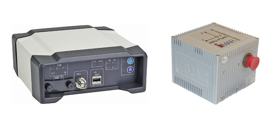
Key components of the NovAtel SPAN GNSS-INS sytem built into the Pegasus:Two include a tactical-grade IMU (the FSAS-EI-SN containing fiber optic gyros and servo-accelerometers, at right), the Propak (at left) that contains the GNSS receiver, one or two survey-grade GNSS antennas, and an optional DMI (wheel mount precision odometer).
There are different value propositions for different kinds of firms with mobile-mapping capabilities. Brad noted that, “at Transcend, we have two Pegasus:Twos; we are doing mainly city modeling and asset and inventory. Quite a few of the other mobile-mapping systems are being used for only design survey [the market they’ve always been in] and can charge a substantial rate per mile, but we can do a whole city at far less per mile. Both are highly viable markets.”
Let’s consider this profit-gaining side of the equation. Many mapping contract prices have been quoted by a user as $1,000 per mile; other contracts for higher-detail deliverables have been reaping as much as $10,000 per mile. About $1,000 per mile seems a fair price when the product is often being mapped at a mile a minute, the data is getting processed at a one-to-one rate, and a lot of feature extraction can be automated. The value added for the more detailed $5-10K per mile is extracting and defining all features for a full design-grade base map, which is much more labor-intensive after capture and processing.
Commitment
Are there keys to successful deployment of mobile-mapping systems beyond how different types of projects pencil out?
“From my personal perspective,” said Brad, “success hinges on the ability to make the investment in human resources … unless you have someone dedicated and this is their only job.” Why?
He explained, “Mobile mapping may be the most difficult solution to implement and do well. You have all of the challenges of traditional surveying, all of the challenges of terrestrial scanning, all of the same types of challenges of aerial mapping—and you have them all at the same time.”
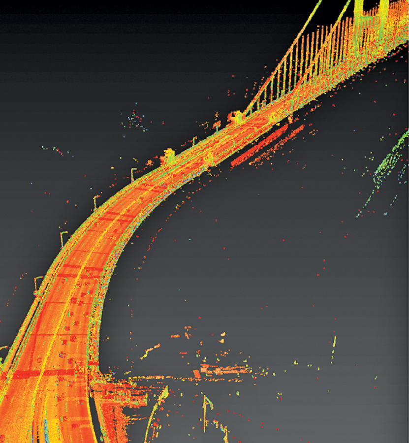
An approach to the Golden Gate Bridge was mapped at highway speed; with integrated GNSS-INS, ground control, video log, and lidar, such systems are capable of providing design-grade 3D topographic models.
His bottom line: “You have to be committed, and you have to have a champion.If you don’t, people will always gravitate back to their traditional work.”
Can the Pegasus:Two do it all? No, it cannot reach out and open that storm drain cover that has been rusted shut for who knows how long. It won’t measure the invert for you either, though some firms are experimenting with pairing trailer-mounted ground penetrating radar with mobile-mapping systems. But on or above the surface, the Pegasus:Two has data capture surrounded.
The Invisible Thread
Much gets written and discussed about the magic of the million-shots-per-second lidar scanners on mobile-mapping systems, calibrated cameras, point cloud and image processing, automated feature recognition, resolution, and range. But the unsung hero of mobile mapping are the little magic boxes that resolve the position of the path the sensor takes through space, extending high precision to every observation the system makes.
A question that crosses the mind of nearly everyone who first encounters a mobile-mapping system is: “How can a GNSS system on a moving vehicle possibly provide sufficient precision?”
The positioning magic at the core of the Pegasus:Two is a NovAtel SPAN GNSS-INS system. It is not as much a black box as you might think (although, understandably, there would be proprietary and patented design elements in NovAtel’s design). Initially it might be hard to believe that this mobile device can, in many instances, resolve more precise locations than your GNSS rover and do so at 40+ km/h.
We asked NovAtel’s Jason Hamilton to demystify the black box for us. “The IMU improves on what GNSS-alone can achieve,” said Hamilton.
He noted the strength of GNSS but also a key weakness: “GNSS can provide a highly accurate 3D position, but you can experience bad positions [outliers] due to multipath, or trees and [structures] disrupting the signals.”
Of inertial (IMU) sensors, Hamilton said, “An IMU measures motion—linear and rotational—and requires no external inputs at data rates of up to 200Hz or higher. An INS integrates IMU data to compute positions that are very stable epoch to epoch but drift over time due to accumulating measurement errors. Combining accurate but susceptible 3D GNSS positioning with stable, high-rate INS motion observations provides very precise, robust positions [at a high rate].”
This gives a high definition of positions along a path: an “invisible thread” along which the time-stamped positions of the registration points of the sensors on the mobile-mapping system can be resolved. The solution uses the strengths of each to compensate for the weaknesses of the other.
Picture a series of successive GNSS positons along a trajectory. In perfect conditions they should fit smoothly along a computed path, they would be well correlated, and it should be easy to derive a time-stamped position anywhere along that path. Conditions change along the vehicle’s path that might block the GNSS signals or present sources of multipath; this will add a lot of noise to the results.
The IMU presents a smooth path in the short range and will make it possible to identify the outliers. About 90% of the errors can be removed simply by processing the GNSS and IMU together. But the beauty of the integrated post-processing is that it can be done multiple times to remove even more error.
“The standard practice,” said Hamilton, “is to process the collected data forward in time, then backward in time, and then forward again: a total of three times.” He noted that this minimizes the error through difficult GNSS conditions; because IMU errors accumulate with time, errors are minimized by optimally combining the position trajectories computed from forward and reverse processing. Don’t worry, the GNSS-IMU processing is not time-consuming and far less demanding of processing power than the lidar observations and images.
Optional components can strengthen this integrated processing. An additional GNSS antenna and receiver can provide a better heading, especially if there is going to be lots of low-speed locations where lower-cost IMUs have trouble determining heading.
For some of the higher-speed applications, a DMI (distance measurement indicator, or odometer) provides well-defined and correlated speed. Hamilton explained that “the DMI is attached to one of the wheels of the vehicle, and a laser reads the speed.” A DMI provides the best benefit in areas where the GNSS coverage is an issue.
Crews often set up bases to collect GNSS data for post processing, or they can download observations from NGS CORS or local RTN. It is not necessary to run the GNSS base data at any rate higher than 1Hz, except in special situations. It has not been shown in post-processing that interpolated high-rate processing is inferior to processing every single high-rate epoch, and this only makes for huge and unwieldy base files.
“Project planning can help determine where ground targets might be desirable to set in advance,” said Hamilton. While some mapping needs might call for dense ground targets, post-processing results will reveal where post-registration points might need to be observed with RTK, total stations, and/or levels.

A screen shot of the comprehensive video log from the mapping operator’s interface: every frame is time- and location-registered, matching the processed point cloud.
Peg-2 Live Crew
We recently tagged along with Shawn Wilson and Adam Baines of Tetra Tech, a multi-disciplined national firm, for a day of mobile mapping in Redmond, Washington. It was a lightly overcast spring day, and the crew was on their fourth day of an expected six days of driving the 288 miles of the city’s roadway corridors, which would yield a 3D model of nearly the entire city.
Wilson and Baines said that they like that their Pegasus:Two is almost completely self-contained and they do not have to attach many components separately. Their particular configuration has one lidar scanner, one GNSS receiver/antenna, the NovAtel SPAN GNSS-INS system, a 1 TB drive, and seven cameras (six around and one fish-eye pointing straight up). The whole unit is about 51Kg, so the pair easily lift it on to a reinforced metal frame built over a standard shell on the back of crew-cab pickup.
The only other components are a laptop in the cab and a battery case/Ethernet hub that sits in the back of the otherwise-empty pickup shell.
The crew uses best practices as recommended by Leica Geosystems, but they’ve also developed their own practices through experience and to suit the specifics of each project.
The days mapping start with, as Wilson explained, “driving some figure-eights in a parking lot we use as a calibrations site. We drive figure-eights large and small, at different speeds, and at different crossing angles.” This step only takes about five to ten minutes.
Today, Adam is driving, and Shawn is giving directions while he’s on the laptop monitoring progress and quality; the Mariners are on the radio giving the Rangers a hard time on the ballfield.
Wilson works from printed directions. “I spent about five days in mission planning. I imported the city’s centerline shape files, looked at one-way streets, and looked at aerial photos to see where there was a lot of canopy if we needed to preset control in those areas, then broke the driving into short segments and printed the turn-by-turn directions.” Wilson views mission planning as critical.
Redmond is a booming, medium-sized city near Seattle, home of the main Microsoft campus and many other high-tech businesses. Most of the roads and infrastructure are relatively new; the suburban streets are lined with a mix of split-level and “McMansion” homes.
Despite this being Washington (with lots of foliage), the crew did not need to pre-set any control (they had some existing control from other ground surveying projects). They were able to download publicly available GNSS files for post-processing from existing permanent RTN and CORS bases that cover the state.
Wilson said, “For most of the suburban streets, we can drive them once, but for large four-lane roads or ones with a lot of traffic, parked cars, or close-in vegetation that can create shadows in the data, we will drive on both directions.”
The city contracted Tetra Tech to drive the entire city for a specific short-term application in mind, but also, as Wilson pointed out, “They plan to use this as the basis for a 3D city. The city uses a software called Lucity, which is an interface with ArcGIS 10.3 for management of city infrastructure.”
The first application Tetra Tech is doing for the city is to use the scans to look for sidewalk panel lifts of over ¼”. “The cool thing about this data,” said Wilson, “is that we can do this extract for the city, but there is a complete set of scans and photos that they can continue to mine for other needs without having to go measure everything again.”
As they drive, Wilson keeps an eye on key performance indicators. One is the discrepancy between the raw unprocessed GNSS and IMU positons; typically, this is under 0.1m, and rarely does the discrepancy stray so far as to warrant re-driving segments. He looks for misfired camera frames, though he noted only one in over an hour of driving. The GNSS status shows if there are extended periods with less than four satellites are in view.
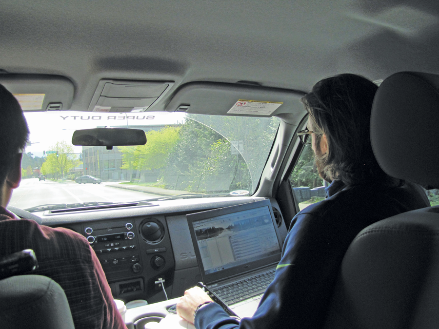
Tetra Tech’s Peg-2 Live Crew: Baines drives while Wilson operates the system and provides driving directions.
Stop signs and lights are not a problem, but if they have to stop and back up (like we did in some tight cul-de-sacs), Wilson said, “that can cause a lot of discrepancies in the scan data, so we turn off the scanner and turn it back on after we turn around. We’ll do a slow crawl after that to give the scanner time to spool up again—around 45 to 60 seconds. This also avoids too much data piling up on the same features and changes the conditions a bit as we crawl.”
Most of the work can be done at posted speed limits; much slower has no gain and then becomes a data-management problem. They can easily run all day on the charged batteries and have plenty of room on the hard drive for the photos and scans.
“Post-processing will probably take a few more days,” Wilson said. “Sometimes I set everything up before I leave for the night and let it cook. We can look at the quality of the processed GNSS and IMU solutions and color code it from green for good to red for bad, overlay this in Google Earth, and look at canopy, etc. This helps us identify areas that we might want to do post-control.”
By post-control, Wilson means, “We find things like the corners of stop bars or concrete panels, the detectable surfaces at handicapped crossings, anything with a well-defined corner. Then we measure those with RTK or total stations and can put positions in and post-process again, tightening everything up.” He figured they might spend an additional day at most shooting post-control points for this project.
“We initially export everything in HPC [Hexagon cloud format],” he explained, “but for the sidewalk study, we are using a [MicroStation-based] software called TopoDOT to do the automated feature extraction, and for this we need to also export LAS [ASPRS laser file] format.”
They have been running their Pegasus:Two for nearly a year but have not had to send it in for a full calibration yet. Wilson said that the unit comes with a canned calibration routine, and, “once we have processed the scans and images, we can check how crosshairs align in the two views on objects or calibration points. One improvement of the Pegasus:Two from older models is that the cameras are integrated into the [housing]; older systems had cameras attached externally and could wriggle around a bit.”
As we drive back to the calibration site, Robinson Canó racks up another dinger for the Mariners, and the crew has completed another successful day of mobile mapping; it has been a good day all around. n