Editor’s Note: The lifespans of valuable infrastructure in both the public and private sectors can be extended far beyond the original design expectations. Upgrades can serve not only to maintain structural integrity and functionality, but also to modernize and boost efficiency.
All too often the design challenge is overcoming the lack of accurate as-built information. Scanning has become the go-to solution for accurate and cost-effective documentation of unique and complex facilities, and projects of this kind have become a growth market for creative and skilled surveyors.
 Located in southeast Chicago, the Calumet Water Reclamation Plant (CWRP) is the oldest of seven wastewater treatment plants of Greater Chicago’s Metropolitan Water Reclamation District (MWRD). Handling wastewater and runoff from southern Chicago and nearby suburbs, the plant is served by the Calumet Tunnel, one of the Tunnel and Reservoir Plan’s (TARP, see sidebar, “A Huge Legacy”) four separate tunnel systems. A pumping station lifts the water from the tunnel to the treatment facilities on the surface.
More than 350 feet underground, large grates known as “bar screens” prevent debris carried by the water from entering the pumping equipment. Access to the screens is via a pair of vertical wet shafts that connect the underground facilities to a service building at CWRP. Roughly 10 feet on a side, the wet shafts also provide temporary water storage during periods of significant storm water runoff.
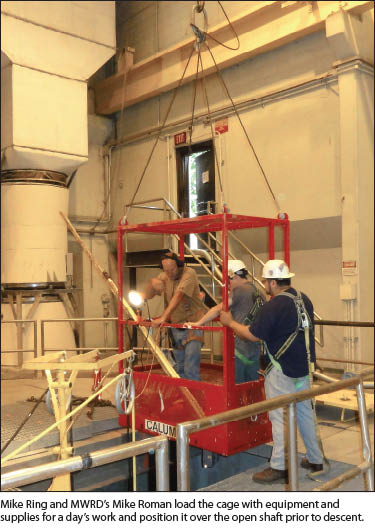
The bar screens must be cleaned at regular intervals. According to Lisa Kursell, principal mechanical engineer for the MWRD process facilities design division, maintenance teams currently visit the screens to manually remove accumulated debris, a difficult, time-consuming process. To access the shafts and bar screens, workers ride in a steel cage that is lowered into the shafts by a crane in the service building.
Constructed in 1985 as part of the TARP system, the bar screens are due for replacement and upgrading. The upgrades include installation of an automated system to clear debris from the screens and bring it to the surface for disposal. In 2013, the MWRD began preparing contract documents to provide to potential bidders for design and construction of the new facility.
“It’s a complicated project that will take place in tight quarters,” Kursell said. “We want to give the contractors as much  information as we can so they know what they are getting into.” She explained that by providing a high level of detail, the MWRD can control costs by helping to reduce unexpected problems during construction.
Lacking detailed as-built information, Kursell contacted Chicago consulting firm Rubinos and Mesia Engineers (RME) to develop the information needed for planning the upgrades for the shafts and bar screens. At the suggestion of the construction staff (and already being familiar with 3D laser scanning), Kursell knew what the technology could do in the horizontal environment of the MWRD’s tunnels. But she didn’t know how it would work in the narrow vertical world of the wet shafts.
RME senior project engineer Ken Nizamuddin contacted Mike Ring, vice president, survey at Environmental Design International, Inc., a Chicago-based firm that specializes in surveying, civil engineering, industrial hygiene, and environmental consulting. Ring agreed to take a look at the project.  After meeting with Kursell and Nizamuddin, Ring devised an approach that would use 3D laser scanning to deliver the information MWRD needed. “We had a lengthy discussion about the purpose of the project and what deliverables they were looking for,” Ring said. “We talked about the equipment, the scanner, the procedures, and how to put it all together. I think they realized there was no other feasible way to get the needed information.”
Nizamuddin said that RME had not used scanning, but he quickly recognized its value for the project. “The District needed an as-built picture of the shafts, and existing drawings weren’t sufficient,” he said. “I was convinced that scanning could provide the information. It could also show any damage to the shaft walls, including protrusions and imperfections down to one-eighth inch.”
The deliverables called for a 3D model of the shaft and service building, together with horizontal cross sections at 10-foot intervals. MWRD would also receive vertical cross sections and photos of the shaft walls. To collect the data, Ring selected a Trimble TX5 3D laser scanner and planned to process the raw data using Trimble RealWorks software.
Getting Down to Work
Access to the shafts required Ring to follow MWRD procedures for safe access in confined areas. He would ride in the cage accompanied by an MWRD ironworker. The cage was equipped with sensors to measure levels of oxygen, carbon monoxide, hydrogen sulfide, and methane in the shaft. Cables for the gas sensors, communications, and electric power connected the cage to the service building, and the MWRD worker was in constant communication with the crane operator. 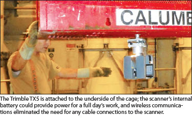 The first task in each shaft was to install visual targets for the scanner. The targets were needed to combine the multiple scans needed to cover full depth of the shafts. Ring cut a simple stencil out of plastic and made the first of many trips down the shafts. Working at intervals of roughly 10 feet, he used white spray paint to paint four or five targets on the shaft walls at each stop. It took a full day to set roughly 180 targets in the west shaft.
The initial scanning was straightforward. With the scanner mounted on a conventional tripod, Ring scanned the interior of the service building, taking care to collect scanning data as far down into the shafts as possible.
When it was time to go vertical, Ring needed to solve two sticky problems. First, he needed to mount the scanner on the cage to enable it to clearly “see” the shaft walls and avoid obstruction by the cage’s metal frame and floor. Second, he needed to stabilize the cage while the scanner was at work.
To hold the cage motionless, Ring used a pair of extendable poles used by painters. “I used some U-bolts and bolted the poles to the side of the cage. When we would get to a certain level to scan I would extend the poles out so they would brace against the walls of the shaft in two directions, providing four points of contact. I would sit down in the cage and wait for it to stop moving. Then I would control the scanner with my Android smartphone using a Wi-Fi connection.” 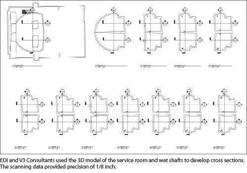 To mount the Trimble TX5 to the cage, Ring took advantage of the scanner’s ability to operate in any orientation. Working with Precision Midwest, EDI’s Trimble representative, they devised a simple method to invert the scanner and attach it to the underside of the cage. With the scanner’s tilt sensor switched off, he could gather the scans and photos without concern for orientation.
Ring said, “I think that the TX5, because of its size, is the right piece of equipment for an application like this. Other scanners are much larger and heavier. I was a little bit freaked out when I first mounted it upside down on the bottom of that cage, because if that thing falls off that’s a lot of money literally down the drain.”
Ring also installed two sets of shop lights on the cage to light the walls. Gathering just a point cloud wouldn’t have needed the additional light, but Ring needed to capture photos as well. “I learned how to light the walls when you’re close to them so it doesn’t wash it out completely,” he said. “I did lose a couple of targets because they were over-lit.” 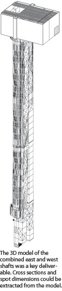 With the scanner securely mounted beneath the cage, Ring, accompanied by the MWRD worker, planned to scan the shaft in one day, but issues with the crane added a half-day to the work. They conducted scans at roughly 20-foot intervals, ensuring sufficient overlap between scans as well as good visibility of multiple sets of targets. Ring needed 19 scans to cover the entire shaft, capturing photos as well as 3D points at each stop. To meet MWRD specifications for precision, he scanned at a density of one-quarter inch at 30 feet.
While waiting for water to drain from the east shaft, Ring analyzed the first set of scans. “I sent RME a screen capture of the scan as it was put together for just the west shaft,” he said. “They seemed genuinely excited about how it had turned out. RME could use the photographs from the scan to inspect the condition of the walls, and I created a publishable format where they could view it in the free Trimble RealWorks viewer. They could view the scenes and actually go through and see the conditions of the walls.”
In working with the first set of data, Ring also decided to paint targets in the east shaft at smaller intervals to improve the work of registering the multiple scans. Three weeks after scanning the west shaft, Ring returned to work in the east shaft, completing the targeting and scanning in two days. The finished data set included more than 650 million 3D points and close-up photographs of the shaft walls.
Rapid Delivery
The final phase of Ring’s work included creating the 3D models and cross-sections. RME and the MWRD called for these deliverables to be in AutoCAD formats, and Ring used Trimble RealWorks to create E57 files to easily transfer the scanning data into the required software. Work to create the horizontal and vertical sections went quickly, and EDI completed their work on schedule.
RME’s Nizamuddin was pleased with the results. “We got what we needed,” he said, noting that the data provided sufficient resolution to identify areas on the shaft walls in need of repairs. “We could come up with rough quantities to say that there are x number of linear feet of cracks that need attention. We got a good feel for the project and what is needed to make the repairs and improvements. This information could not have been obtained without scanning.”
Kursell said MWRD will present the scanning data at pre-bid conferences. By using the scanning information, contractors can better understand the scope of the project and develop ideas to operate in the shafts’ tight working space. “It’s important to prevent surprises as much as possible,” she said, “and that means getting good information up front.”
The scanning data will save time and money as the project moves into the bidding phase, with the real value coming during construction by optimizing contractor performance. “Difficult problems often can be solved by using technology that already exists,” Kursell said. “You just need to apply it in a different way.” As Mike Ring has learned, sometimes you might even need to turn things upside down.
SIDEBAR 1
A Huge Legacy
For more than 100 years, Chicago-area agencies have provided clean water for residents and businesses. Early water management efforts consisted of directing sewage and storm runoff into Lake Michigan. But as the population grew, the lake proved ineffective in handling the city’s wastewater.
When sewage in the lake threatened to contaminate the pumps that provided the region’s fresh water, the city of Chicago in 1834 began nearly 200 years of water management projects. By 1848, the Illinois and Michigan Canal was completed to divert some sewage from the Chicago River; in 1900, engineering projects reversed the flow of the river, carrying the sewage away from the lake. These efforts helped, but growth in Chicago and the surrounding communities demanded new, larger solutions to handle the region’s wastewater.
Like many older cities, Chicago’s sewage and storm water share a combined collection system. Because storm runoff gets mixed with sanitary sewage, every drop of water must be managed and treated before it can be released back into the environment. Compounding the problem, heavy rainfall can overwhelm the collection system and result in combined sewage overflows (CSO), causing sewage to back up into streets, homes and businesses. The way to prevent CSO is to capture all water during storms and store it until it can be treated and released. However, this process presents enormous challenges for large urbanized regions like Chicago.
Today, the MWRD handles Cook County’s sewage and storm water management. The MWRD provides collection and treatment for Chicago and 51 suburbs covering an area of 875 square miles, of which 375 square miles contains combined sewers.
To facilitate compliance with state and federal water quality standards by protecting Lake Michigan from raw sewage pollution, the MWRD in 1972 adopted TARP. Currently estimated to cost nearly $4 billion, TARP’s primary components include three reservoirs to capture and store water before it can be treated and released. The reservoirs will be fed by a series of tunnels connected to the MWRD and municipal collection systems. With construction expected to extend to 2029, several major TARP components are already in place, including 109 miles of tunnels and one reservoir. System storage capacity is planned at 17.5 billion gallons upon completion.
SIDEBAR 2
Adding Scanning to Your Toolkit
Because new technologies can change rapidly, EDI has taken a stepwise approach to bringing scanning into their business. Ring explained that while EDI has not purchased a scanner, the company does own a license for Trimble RealWorks software. By having the software in-house, EDI technicians can spend more time learning the routines and becoming efficient at the 3D data processing and management. Full-time access to the software also makes it easy for EDI to extract new information from existing data sets.
This approach allows EDI to maintain high proficiency while renting scanners on a project-by-project basis. For example, Ring has rented scanners for use on a railway bridge and in multiple projects to gather data for improvements in a refinery.
The company is promoting its scanning capabilities to its clients with the goal of establishing a steady stream of work. At that point, EDI would expect to purchase a scanner, according to Ring. He said maintaining the software workflow is important and allows him to blend scanning data with information from EDI’s other Trimble surveying systems.
“We’re finding ways in the survey department to incorporate scanning into our work flow so it’s not a specialty thing,” Ring said. “There are specific places for scanning to go. If we can find a way to use it and to make the work process a little more efficient, then that’s what we’re going to do. And if there’s also something we can provide to the client that makes a more valuable deliverable, then obviously we’re going to do that as well.”