When evaluating automated versus conventional deformation monitoring for a major rail project in Slovenia, automated clearly wins.
Editor’s Note: PSM has examined several automated deformation monitoring case studies; due to technological advances, automated monitoring has gone mainstream. The following adaptation of an academic paper provides a direct analysis of project operational considerations and cost comparisons. Intuitively, it should be obvious that automated monitoring saves costs, but this article makes a strong case for such assumptions.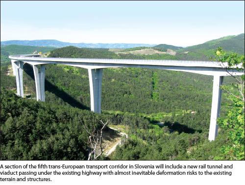 The evaluated project is a new railway route in Slovenia, part of the fifth trans-European transport corridor from Divacˇa to Koper. Most of the route (80% of 21km) will be built through tunnels and viaducts (scan the code at the end for a video of the simulated route); therefore, this project will significantly affect the stabilization of the ground and existing structures in some areas.
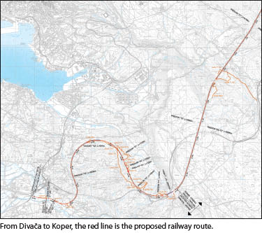
Based on past major construction projects in the area, we know that any disturbance to the ground could create a reaction in the rock mass. Safety and security is becoming increasingly important; therefore, monitoring of displacements and deformations of buildings and activities in the affected space is a necessity.
The purpose of monitoring is performance measurement and subsequent identification of changes and deformations in the environment or the facility. Often it is necessary to analyze the measured data immediately and inform all stakeholders in the project if movement exceeds certain agreed-upon tolerances. Monitor—analyze—inform. Geotechnical monitoring means recording and analyzing the event almost simultaneously, as well as the post-processing analysis of correlations. Monitoring and deformation analysis present some of the most sophisticated challenges in the civil and mining industry today, as they require maximum precision, maximum reliability, automatic measurements, and advanced computation and analysis, as well as having to make this data available to all partners in the shortest time possible.
Features Monitored
 There will be eight tunnels (T1-T8) and two viaducts (V1 and V2) along this stretch. In the preliminary displacement monitoring project, the most challenging areas of the route are the highway viaduct Cˇrni Kal, the area of the future railway viaduct Gabrovica, and the area of the highway that lies above the proposed railway tunnel with a relatively low enclosure.
In order to ensure appropriate security, a reliable and fast monitoring solution for the ground is recommended with a sufficient amount of data that can be the basis for immediate action during construction to prevent the development of deformities in the wider area. Areas where the rail route overlaps with the highway route and where some earthworks will be performed in the immediate vicinity of highway construction are viaduct V1 and tunnel T4.
The area of the viaduct Cˇrni Kal is designed with three pillars that are 80m high, four at 120m, one each at 140m, 75m, 60m, 40m, and three more at 50m. Expansion joints, which are mounted only on the final braces, allow movement up to 72cm on each side of the viaduct. The foundations of the pillars are on the edge of Karst limestone rock, in the lower valley, on ancient marine sedimentary terrain.
The railway viaduct will be built over the Osp valley at a height of 10-60m. The existing viaduct Cˇrni Kal will be crossed at an angle of 30°, between the fifth and sixth viaduct pillar. The railway construction will cross 30m below the existing viaduct. The foundation of the viaduct pillars are anchored in 10m-diameter wells, dug at least 4m deep into the solid sandstone.
Specific Geotechnical Hazards
 Tunnels T3 and T4 will be excavated on the slope and in the rock mass below the highway. In addition to the standard strain and destructive effects on the construction area, other problems may also occur, such as crushing the supporting rock. Sandstone rock can break due to water exposure or mechanical stress in the flaky rock debris, but it can even stress supporting clay and mud. The rock mass may also swell; potential swelling may be higher than expected in tectonic material or sandstone rocks.
There may also be a loss of stone plates and blocks of rock. Due to the gentle dip of the layers, this may lead to the failure and loss of the rock plates, blocks, and weak rock mass, and instant and unexpected failures from the tunnel ceiling may occur from competent rock. There is a possibility of the slopes sliding and the rock mass volume translating to surface deformation, such as displacements that can trigger landslides.
Monitoring Specifications
This project requires that 3D displacement measurement is conducted with conventional methods. Direction and elevation tolerance control are required as well as the phase-launching method of roadway construction between pillars (deflection tolerance is ±3mm for the project; the difference within beds in the same pillar can be 1mm).
Observation is also required for the axis of the roadway construction. For deformation control of the pillars, an additional system of observation is also required. A complete survey of the site will be completed before the start of the construction; there can be no reliance on as-built records. Expected displacements of structures at the top of the pillars are 3-6cm.
According to all data from the project documentation, the possibility of deformation of the highway body under which tunnel T4 is passing is already evident. The motorway section from the exit of Cˇrni Kal to a small overpass, 500m west, is the highway area influenced because of tunnel T4 excavation. Excavating parallel to the slope may cause rock to fall from the ceiling of the tunnel due to the position of the layers in the excavation area and may consequently cause surface deformation due to voids from these displacements in the tunnel.
The Automated Solution
 An automated system for monitoring movement for this project is based on GNSS technology and augmented with optical measurements. Automatic monitoring and detection of movement in real time is the most suitable for the area of the V1 viaduct and the area of the influenced surface above tunnel T4.
The availability of real-time data in this case would mean optimal control of the construction site and would also establish a warning system that would detect changes and movements on specific points in the area. This means an alarm system to protect people and property, as well as to inform design changes for the contract work performed at the site.
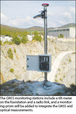
The automated system is comprised of 12 stations and a GNSS receiver with a 3D prism in combination with co-located inclination sensors. Also included are two robotic total stations, at least 30 monitoring prisms, a GNSS reference station, plus software packages for sensor management and the managing, processing, and analyzing of the data.
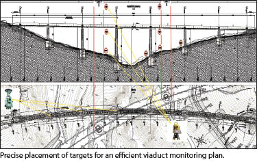
The optical targets are placed on the pillars of the motorway viaduct at its lowest, middle, and highest points. This method allows monitoring of pillars in the event of inclination, subsidence, or foundation slipping. Similarly, the railway viaduct pillars and roadway structure will also be equipped where it is necessary to monitor the situation between construction stages.
Optical measurements are combined with the GNSS system, which is placed exactly at the supporting point of roadway construction pillars. The GNSS system is capable of monitoring the displacements correlated to weather conditions, seismic movements, and vibrations from the highway viaduct construction. The robotic total station, in this case, is also used to control the direction of the railway viaduct construction and follows the installation formwork platforms during the concreting of pillars and roadway structure of the railway viaduct.
The reference point for the GNSS system must be outside of the excavation-influenced area in naturally lower ground. The points for the observation area are placed above tunnel T4, below the tunnel route in the niche between the roadways. On the 17km-to-18km route section, the overlap length of objects is 600m; a monitoring station will be installed every 60m-70m, which represents 10 GNSS stations also equipped with 3D prisms. They allow connection with total station measurements that can be used in special cases or for any other measurements in the region where optical measurements are provided.
The GNSS monitoring system on the surface may also be used to reference the underground system, which is required for geotechnical and optical measurements in tunnels T3 and T4. In this case, underground measurements can always stay connected with up-to-date reference data.
Costs for the Conventional Option
 Start-up costs for such a project are around $33,800, but that does not include measurement equipment provided by the contractor of the geodetic elements. Conventional work would require five people, two operators each on two crews and one data analyst in the office for daily/weekly report preparation.
Costs of geodetic quality displacement observations range from between $530 and $930 per day (based on local labor rates). Monthly, that ranges from $15,600 to $27,300 during the construction period. If the construction is estimated for 24 months, this means around $520,000, with the assumption that the viaduct and tunnel require up-to-date daily information for each subject area and feature as construction progresses. It should be noted that less-frequent measurements do not mean incomplete monitoring; it means fewer data delays in recording and trend-line analysis.
Costs for the Automated Option
The largest cost is the upfront purchase of the GNSS system: $260,000 to $364,000 for the equipment and software described here. This up-front investment enables automated measurements and reporting with substantial savings in labor costs. It should also be noted that the equipment can be used on subsequent projects.
The proposed automated monitoring system, used during the period of construction and the initial operation period of the completed infrastructure, has advantages in several key areas: It is economically viable and desirable, technically much more advanced and reliable (in previous projects the accuracy was between 1mm and 2mm in detecting 3D movements). It works in real time and has a sophisticated analysis of the time series of events. And it is partner-friendly, easily accessible through the entire project period even remotely, and retains a full history of all movement.
A Timely Choice
Monitoring technology has come a long way in a relatively short time, with construction and mining companies realizing real benefits from using combinations of displacement monitoring systems to get a better understanding of what is happening under the ground or on the surface during excavation, construction, and operating. Today’s sophisticated monitoring systems are a relatively new addition to the civil, survey, or mine engineer’s toolkit; selecting the most appropriate and economical system for the project will become an increasingly important challenge in the future.
We extend a special thank you to the Slovenian State Railways and Simon Kovacic for providing project information for this article.