Judicial, geodetic, and practical considerations
Editor’s note: Mention “coordinates” in relation to cadastral surveying to a group of land surveyors and you will likely raise eyebrows and voices—often the conversation leads to a mischaracterization of the issue as somehow being “coordinates versus monumentation.” Although many countries (and even states and individual jurisdictions in the U.S.) have already ruled coordinates as an accepted form of boundary evidence and with many coordinate-based cadastres under way around the globe and even I parts of the Unites States, there has been general confusion about and avoidance of the subject.
Several factors are driving the need to come to grips with the subject, and soon. These include the use of relatively newer measurement technologies like GNSS (and those on near-developmental horizons). These apply geodetic principles and methods to the resolution of even the relative spatial relationships between local references and monumentation, but also there’s a need for them simply an an adjunct to physical monumentation that is susceptible to damage, disputes, and in some cases shrinking budgets. The following is an outstanding paper by Teresa Smithson who has researched both the judicial and practical considerations of coordinates as boundary evidence.
 In the event that no monumentation remains of an original survey, the retracing surveyor needs to weigh all of the evidence to best determine the original intent as described on the face of the property legal description. Legal doctrine is well established that the role of the retracing surveyor is to “follow in the footsteps of the original surveyor.” In order to do so, evidence may include deeds, written field notes, plats/maps, and physical evidence on the ground. However, the courts have historically included only a surveyor’s bearings and distances as part of the measurement description evidence; coordinates are not recognized as legal evidence. Today’s surveys are often performed using Global Navigation Satellite Systems (GNSS), where geodetic coordinates are the primary tool for setting and locating monuments. Over the past 20 plus years of technological improvements, GNSS has now become a standard method for establishing points in land surveying. In addition, many jurisdictions require new subdivision plats and/or resurveys to be submitted in electronic form and for them to include ties to the county/state spatial reference networks, which provide a wealth of coordinate evidence for boundary retracement. Coordinates may be the best available evidence of a boundary corner location when corner monumentation is lost. Therefore, in judicial findings of fact coordinates should have equal or higher legal weight to angles and distances in establishing property lines when the corner monuments are lost.
Coordinates and the Priority of Calls
Case law has established vector measurements, sometimes referred to as “metes,” “angles and distances,” or “courses and distances,” as factual evidence for the location of a property boundary, albeit last-resort evidence. However, coordinates as boundary evidence have traditionally been regarded with very low to non-existent credibility by the courts and are seldom mentioned in court rulings.
According to a Maine court, “We consistently have held that what boundaries a deed refers to is a question of law, while the location of those boundaries on the face of the earth is a question of fact. If facts extrinsic to the deed reveal a latent ambiguity, then we determine the intent from contemporaneous circumstances and from standard rules of construction. A basic rule is that boundaries are controlled, in descending priority, by monuments, courses, distances, and quantity, unless this priority produces absurd results. The physical disappearance of a monument does not end its use in defining a boundary if its former location can be ascertained” (Theriault v. Murray, 1991). This priority of evidence has been affirmed repeatedly by the courts since the 1800s: Beckley v. Bryan and Ransdale [1 Ky (Ky. Dec.) 91 (1801)], M’Iver’s Lessee v. Walker (Overton’s Tennessee Reports, Vol II, 1814), Bradford v. Pitts, 2 Mills. Const. Rep. 115 (S.C. 1818), Cherry v. Slade’s Administrator, 3 Murph. 82 I N.C., 1819, Riley, administratix, & c v. Griffin, et al, 16 Ga. 141 (1854).
The tools, methods, and procedures employed in the practice of boundary surveying are not static or immutable; these are dynamic, and it is not without precedent that judicial views may adapt to follow. For example, the growing usage of global navigation satellite systems (GNSS) by today’s land surveyor is changing boundary survey procedure standards (where practical and appropriate) by implementing a coordinate measurement system. As stated in Clark on Surveying and Boundaries, sixth edition, “The technical field of surveying has progressed faster than the courts’ acceptance of the results of this technology … Before the courts will accept any new scientific method, it must be proven to the court’s satisfaction that the results are dependable” (Robillard & Lane, 1992, §31.09).
After more than 20 years of development and refinement of GNSS usage for boundary surveying, the technology has become dependable with repeatable results. In Boundary Control and Legal Principles, Brown recognizes the importance of precisely determined coordinates: “If a monument is found and the coordinates of the monument are precisely determined by an acceptable method, and then the monument is later lost, the coordinates so established will probably form the best available means of re-establishing the former position or providing an area of search to look for monuments.” He includes newly set monuments by stating, “If an original monument is set …, the coordinates will probably be the best means of restoring the corner, if lost.” He continues, “Coordinates are an informational aid …” (Brown 1995, pp. 285-286). Since 1995, the technology has surpassed this basic tenet, and coordinates have become the virtual monument.
The courts should consider coordinates as factual evidence at least equal to vector measurements in establishing lost original boundary corners. This assertion is based on the facts that 1) accurate GNSS coordinates are based on spherical geometry, not plane geometry (used by more traditional surveying methods), and therefore they more accurately reflect how the boundary lines were either created or retraced using geodetic-quality GNSS equipment; 2) geodetic receiver GNSS coordinates are reliable, dependable, accurate, and precise when properly collected and defined using a geodetic datum; and 3) there is a plethora of metadata and coordinate information on surveys filed with local jurisdictions, especially those inserting surveys into the local geographic information system (GIS), that provide valuable evidence for retracing a survey.
Spherical Geometry and Geodetic Coordinates
GNSS’s primary coordinate system is based on a three-dimensional model where the X and Y axes represent length and width and the Z axis is aligned with the International Reference Pole (IRP). The model is known as Earth Centered Earth Fixed (ECEF) with the point of origin (X=0, Y=0, Z=0) at the Earth’s center of mass (Figure 1).
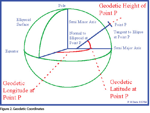
This coordinate system cannot directly be used as grid coordinates for boundary surveying. Overlaid onto this ECEF system is an ellipsoidal model from which secondary coordinates are derived. These secondary coordinates are the spherical or geodetic coordinates known as latitude, longitude, and ellipsoid height (Figure 2). A tertiary set of plane two-dimensional grid coordinates (i.e. projection from geographic to “grid”) is derived from the geodetic coordinates and requires clear parameter definitions such as projection and elevation scale, central meridian, point of origin, transformation parameters, and convergence in order to calculate true ground distances. These tertiary grid coordinates are the projected coordinates familiar to land surveyors and engineers and are a source for line bearings and distances on a two-dimensional plane.
This process of GNSS coordinate derivation contrasts to that used in conventional plane surveying using total stations or other historical measuring devices. In plane surveying, the surveyor begins by establishing a point of beginning and defining a basis of bearings. The surveyor then traverses a course of angles and distances from which all other ground coordinates are calculated and used as placeholders.
This method is a dependent method, where each point or monument is subject to error of the other points. Due to this dependence, errors are potentially magnified as the traverse proceeds through the description. It is these conventional angles and distances based on traversed ground coordinates that the courts have looked to in their priority of calls as the best available boundary line evidence when corner monumentation has been lost, even when the lines are not traversed.
In contrast, when you obtain geodetic coordinates using GNSS equipment, each point or monument is independently observed without reference to the other points, with all points referenced to one or more accurately determined reference stations. In this method, the GNSS geodetic coordinates are the primary means for establishing the boundary corners, and the bearings and distances are by-products of the process. Errors remain isolated to each individual point.
The priority of calls in boundary evidence is based on the doctrine that “the original survey as it was actually run on the ground controls” and is firmly entrenched in American law (United States v. Doyle, 1972). Texas appellant court reaffirmed this doctrine when it stated, “The primary objective in locating a survey is to “follow the footsteps of the original surveyor,” by which is meant to trace on the ground the lines as he actually ran them in making the survey. “When the actual lines run by the surveyor can be found, they constitute the true boundary and cannot be made to yield to course and distance calls” (TH Investments v. Kirby Inland Marine, 2007).
What if the “actual lines” are not “run” as in conventional plane geometry surveying but are established using GNSS technology and geodetic coordinates? Angles and distances are no longer the primary method of measuring the boundary; they are now the byproduct. The coordinates points are now the primary measuring tool with dependable and repeatable results.
Dependable and Defensible Coordinates
The dependability of GNSS surveying is well established within the scientific and surveying communities. Michigan Technological University lists the many applications for precise GNSS: geodetic control, deformation surveys, photo control-ground and in-flight control, hydrographic surveying, boundary retracement and establishment, topographic surveys, satellite imagery rectification, environmental issues, and agriculture and forestry management (http://www.tech.mtu.edu).
The integration of GNSS into nearly every aspect of measuring the Earth is, in part, a result of the user’s ability to rely on the results, an expectation that is supported by a well-defined reference network. The National Geodetic Survey (NGS), a branch of the National Oceanic and Atmospheric Administration (NOAA), maintains a National Spatial Reference System (NSRS). “The NSRS is the consistent coordinate system that defines latitude, longitude, height, scale, gravity, and orientation throughout the United States and its territories” (National Geodetic Survey, 2012).
The NSRS provides a national reference frame with centimeter accuracy for land surveyors to use anywhere in the United States that is repeatable and provides documentation in order for it to be used in a subsequent historical context. Documentation for the continuously operating reference stations (CORS) can be downloaded from the NGS website. This documentation includes the ECEF, geodetic, and grid coordinates for each station, along with other values required for calculating geodetic-to-grid conversions. Also available from NGS are electronic data file processing and reference frame information.
All of these tools provide a historical record so that a retracing surveyor can accurately identify the conditions that existed at the time the geodetic coordinates were originally established. While GNSS may at present not provide sufficient precision for very short boundary segments to meet standards for limited types of urban surveys in specific jurisdictions, it is very likely that such precision will be met by multi-channel, multi-constellation GNSS and new ground and satellite augmentations systems in development, which is all the more reason to explore coordinates as boundary evidence. That future may be here sooner than we think.
As evidence of the GNSS accuracy, the University NavStar Consortium (UNAVCO) uses GNSS equipment throughout the world on projects requiring millimeter-scale surface motion measurements such as tectonic plate boundary observations and terrestrial geodetic reference stations (http://www.unavco.org/crosscutting/cc-data.html). This network of well-defined and -published reference stations ensures coordinates are uniform and consistent. As long as proper coordinate definition is provided, a land surveyor following in the steps of the original surveyor could accurately retrace the original GNSS survey within acceptable tolerance. Where land may shift or drift in high fault areas, the coordinates can still be used by utilizing difference in coordinates similar to that used with angles and distances.
Coordinates in State and Local Jurisdictions
In the 1930s, the U.S. Coast and Geodetic Survey developed the State Coordinate System. The State Plane Coordinate System (SPCS) was created to address the problems of insufficient monumentation and the distortion created from geodetic monuments being too far apart. In a manual for surveyors, NOAA expressed its concerns about maintaining a dependable network of reference monuments:
“The utility of the [survey] method employed depends in a great measure upon there being recoverable at future times, monuments at stations from which surveys can be run to determine the ground positions corresponding to the coordinates of points whose monuments have been obliterated or destroyed. But as original survey monuments decay and disappear and the stations they represented are restored by survey methods, these restored stations themselves become the bases from which other restorations are made. And with each subsequent restoration, the accuracy of the result is diminished, since it is affected by the errors of the original survey combined with the errors of the restoration survey or surveys. Eventually, even a good survey of a limited area with only its own monuments to preserve its ground location will, by loss of original monuments and errors of replacement, become little more than a paper record, beyond the power of a surveyor to transform into a ground pattern of monumented lines without the aid of a court decision prescribing a legal method of construing conflicting records and interpreting survey discrepancies” (Mitchell and Simmons, 1945).
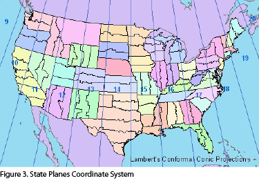
To address this insecurity, a national system was implemented, and 48 of the 50 states plus Puerto Rico and Guam now have a statute-defined SPCS. In addition, many local jurisdictions have control networks tied to the SPCS and the NSRS (Figure 3). The SPCS is a set of 124 geographic zones that use a grid coordinate system within a small enough region that use of the coordinates provides an error less than 1:10000, which is accuracy sufficient for land surveying (Stem and NOAA, 1990).
After the establishment of the SPCS, many states enacted statutes recognizing the use of state plane coordinates for survey control annotated on survey plats and for legal descriptions.
California, for example, recognizes state plane coordinates for property identification: “State plane coordinates may be used for property identification on any map, survey, conveyance, or other instrument which delineates or affects the title to real property or which delineates, describes, or refers to the property, or any part thereof” (California Public Resources Code, 2011).
Texas Natural Resource Code requires that all field notes will include “State Plane Coordinates based on the Texas Coordinate System of 1927 or the Texas Coordinate System of 1983 values for the beginning point on the survey with appropriate reference to zone, mapping angle, grid distances, acreage and the N.G.S. Station to which the survey is tied” [Texas NRC Ch. 21(C), §21.041(5)].
The Commonwealth of Virginia accepts the use of SPCS as a valid legal description: “For purposes of describing the location of any survey station or land boundary corner in the Commonwealth of Virginia, it shall be considered a complete, legal, and satisfactory description of such location to give the position of said survey station or land boundary corner on the system of plane coordinates defined in this chapter. Nothing contained in this chapter shall require any purchaser or mortgagee to rely on a description any part of which depends exclusively upon either Virginia Coordinate System” [1946, p. 168; Michie Suppl. 1946, § 2849(8); 1984, c. 726.] (Virginia Code Title 55, Ch17, §55-296). 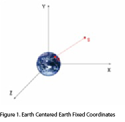 However, the perpetuation of monumentation continued to be a problem. Highway projects and other development projects completely destroyed many of the reference monuments. The development of a global navigation satellite system and the subsequent addition of GNSS reference stations have now replaced the original SPCS network.
The perpetuation of this new GNSS network is more assured with communities establishing local networks referenced to both geodetic coordinates and the SPCS. The development of local control networks is an essential component for the implementation of GIS (LIS, digital cadastres, et al.) for land use administration. The benefit to this essential local control is that the local jurisdictions are vested in the protection and perpetuation of control monumentation or reference points. This ensures continuity of consistent control points and historical documentation for identifying the correct coordinates in time.
With a more reliable control network in place, local jurisdictions using a GIS may require all survey plats, retracement boundary surveys, and/or new subdivisions to be submitted in electronic form with ties to the local network, SPCS, or NSRS. Such records can be a valuable source for retracing the original survey as well as providing historical information for re-establishing a lost corner. The GIS files also contain valuable information in addition to the property coordinates, such as deed history, easements, rights of ways, and other records that provide chain of title and property rights evidence—all tied to a unified coordinate system.
In 2012, the U.S. Court of Appeals for the Fifth District ruled that an exhibit created in a GIS that “ha[s] embedded within it the GPS coordinates for each specific location and boundary line depicted on the map” satisfies the Statute of Frauds. In doing so, the court found that the GIS exhibit “contains enough descriptive information which, when considered in connection with the attempted written description make[s] location of the land possible.”
 Although the coordinates were not being used in and of themselves for the re-establishment of property corners, the case is noteworthy in that the court accepted the GIS coordinates as being representative of the legal documents conveying property rights. An important statement made by the court was that the statute of frauds “does not require that the agreement identify the property to be conveyed by metes and bounds. Rather, state courts have acknowledged that other means of identification may suffice to achieve ‘reasonable certainty’” (Coe v. Chesapeake Exploration LLC, 2012).
The use of coordinates as the best available evidence for a lost boundary corner is not changing legal doctrine; it is upholding it. The legal test for retracement does not require the surveyor to use specific tools—no one is expected to perform a survey using a Gunter’s chain—but the evidence weighed during legal decisions needs to match the methods used by the original surveyor. GNSS methods are different than plane surveying methods, procedurally and mathematically. When retracing the original survey, it is important to understand whatever methods were used to establish the corners and to “follow in the footsteps of the original surveyor.”
GNSS coordinates, when properly defined, are both accurate and precise and can be easily retraced by subsequent surveyors. Historical documentation is readily available to account for changes in datum, continental drift, or other shifts. In addition, coordinates have been accepted for many years by state statue and local governments as a means of identifying property.
 GNSS coordinates are an increasingly accurate and precise means of defining boundary corners and relocating those corners during retracement. When Earth-centered tools are used as the primary method for setting a lost corner, or if it is available in a previous retracement record, coordinates should prevail over vector measurement as the best available evidence.
SIDEBAR
xyH&t
Geodetic values must be considered as “4D”: the “xy” (northing/easting or lat/long), plus the “h” height (typically the height above the applicable ellipsoid), and (of critical importance) the “t” or time/date/epoch. A published set of coordinates for a given reference point may change over time, from tectonic velocities and from new realizations of the geodetic reference framework, which is why good documentation and metadata are required.
With proper documentation, a future surveyor can use tools such as the online HTDP (Horizontal Time Dependent Positioning) tool provided by the NGS to derive a current versus historical reference. Such tools may soon be implemented to run on-the-fly in your data collector; to accommodate such capabilities a transformation message has been added to RTCM standard for transmitted RTK corrections beginning with RTCM3.1, enabling near-future users to be able to tap into databases of geodetic and time-dependent transformations and projections. This is only going to get easier.
The use of coordinates does not necessarily void the requirement of bearings and distances on a plat; this information is essential for visualizing the dimensions of the boundaries and maintaining robustness. Nor do coordinates usurp established law placing called-for natural and then artificial monumentation above all other calls in establishing the property lines.
In order for the courts to accept coordinates as the best available evidence in replacing lost corners, the surveyor needs to properly identify the datum and epoch for the coordinates used. If geodetic coordinates are depicted on a plat, the documentation could be fairly simple: ellipsoid, International Terrestrial Reference Frame (ITRF) solution, and any reference stations or control points used along with their respective coordinates in the same datum, plus the dates of observation and derivation. If local or SPC grid coordinates are depicted on a plat, the required information becomes greatly complicated. In order to retrace grid coordinates, the projection must be defined either by name, such as “Colorado SPCS North” or “UTM13S”, or defined by its parameters: central meridian and /or basis of bearings, mapping and elevation scale factors, point of origin, and any transformation factors. Unless the survey is conducted in an area close to zero elevation, it is recommended that geodetic coordinates are provided on the plat in lieu of state plane coordinates modified for elevation. As professionals, our concern should be with the perpetuation of our surveys and providing as much evidence as possible to enable our surveys to be retraced long after our demise.
References
Brown, Curtis M., Robillard, Walter G., Wilson, Donald A. (1995). Brown’s Boundary Control and Legal Principals, Fourth Edition. New York: John Wiley & Sons, Inc.
California Public Resources Code (2011). Division 8 Surveying and Mapping, Chapter 1 California Coordinate system, §8814. Referenced on 2 December 2012. http://www.leginfo.ca.gov/cgi-bin/displaycode?section=prc&group=08001-09000&file=8801-8819. Note – Same language is contained in the 2008 code.
Coe v. Chesapeake Exploration LLC, 11- 41003, U.S. Court of Appeals for the Fifth Circuit, Sep. 12, 2012.
Michigan Technological University, “GPS Datum and Coordinates.” Referenced on 2 December 2012. http://www.tech.mtu.edu/courses/su4100/Course_Material/GPS%20in%20Local%20Surveys.pdf
Mitchell, Hugh C. and Simmons, Lansing G., (1945) U.S. Department of Commerce, Coast and Geodetic Survey, The State Coordinate Systems (A Manual for Surveyors). Special Publication No. 235.
National Geodetic Survey (12 July 2012). “The National Geodetic Survey Improves the National Spatial Reference System with Simultaneous Major Product Releases.”, Referenced on 1 December 2012. http://www.ngs.noaa.gov/web/news/NA2011_Announcement.shtml
Robillard, Walter G., Bouman, Lane J. (1992). Clark on Surveying and Boundaries, Sixth edition. Charlottesville, VA: Michie Company.
Stem, James E., Department of Commerce, NOAA (1990) “State Plane Coordinate System of 1983.” March 1990. Referenced on 2 December 2012. http://www.ngs.noaa.gov/PUBS_LIB/ManualNOSNGS5.pdf
TH Investments v. Kirby Inland Marine, 218 S.W.3d 173, 204 (Tex.App.2007).
Theriault v. Murray, 588 A.2d 720, 721, 722 (Me.1991).
UNAVCO, “Data.” 8 August 2012, 1 December 2012. http://www.unavco.org/crosscutting/cc-data.html
United States v. Doyle, 468 F.2d 633, 636 (10th Cir 1972).