In Part 2, I look at the effect that convergence of the meridians has on traverse azimuths and discuss the accuracy of azimuths determined by GNSS surveys. In Part 3, I look at the differences between observed horizontal distances, geodetic distances, and mark-to-mark distances, which are typically listed in GNSS adjustments.
 When we obtain observations in the field, they are taken with respect to gravity. If you have been following along in this sequence of articles, by now you know that gravity helps determine the geoid but not necessarily the ellipsoid. The ellipsoid is our mathematical surface for all horizontal control. In a previous column I present how geoid height is the difference between orthometric height (elevation) and geodetic height. But what other differences affect surveying observations?
Deflection of Vertical
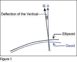
Positions determined with respect to gravity are known as astronomical positions. They are determined from the normal to the geoid, which is marked as A in Figure 1. Positions determined with respect to the ellipsoid are known as geodetic positions. They are determined with respect to the normal to the ellipsoid, which is marked as G in Figure 1.
 Since we level our total station with respect to gravity, we have aligned our instrument with respect to the normal to the geoid (A). These are known as astronomical observations. However, GPS observations and geodetic positions are determined with respect to the ellipsoid, and therefore G.
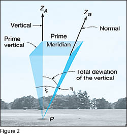
As shown in Figure 2, the zenith (ZA) of an astronomical location is determined by the direction opposite the direction of gravity at this location. The zenith (ZG) of a geodetic location is determined by the direction of the normal to the defining ellipsoid. The difference between these two zeniths is known as deflection of the vertical.
Typically, the deflection of the vertical is given by two angular components. They are designated by the Greek letters ξ (xi) and η (eta). The component of the deflection of the vertical in the north-south direction is ξ and η is the component of the deflection of the vertical in the east-west direction.
 The ξ component is positive when the astronomical zenith is north of the geodetic zenith, and the η component is positive when the astronomical zenith is east of its geodetic counterpart. This means that if geodetic angles are desired, we need to correct conventional instrument observations, which are oriented with respect to the gravity and the geoid, to the normal of the ellipsoid.
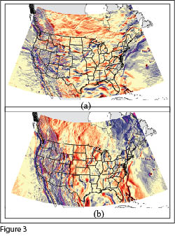
As shown in Figure 3, throughout the United States the size of these components varies with ranges in both ξ and η from −54″ to +58″. The Nationa
l Geodetic Survey (NGS) has a model, called Deflec12A, for computing the deflection components from the current Geoid12A model. It can be found at ngs.noaa.gov/cgi-bin/GEOID_STUFF/deflec12A_prompt.prl.
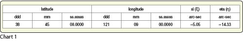
This supporting software allows users to determine the deflection of the vertical components given their geodetic position. To use this interactive page, you simply enter the latitude and longitude for the position of your instrument. Since the geoid changes modestly over a small area, approximate geodetic coordinates are typically adequate. For example, the deflection of the vertical components slightly east of Sacramento, California in Granite Bay using Deflec12A are given in Chart 1.
Corrections to Zenith Angles, Azimuths, and Horizontal Angles
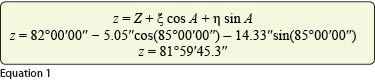 From the Deflec12A model using the aforementioned location, we see that the astronomical zenith is south and west of the geodetic zenith by 5.05″ and 14.33″, respectively. Assume an observed zenith angle, Z, is 82°00′00″ along a line with an azimuth, A, of 85°00′00″; this means that the equivalent geodetic zenith angle, z, at this location is Equation (1) where A in Equation (1) can be either the geodetic (α) or astronomic azimuth (A) of the line. Thus, the geodetic and astronomic zenith angles at this location differ by about 14.7″.
Thus, do not expect zenith angles derived from a GNSS survey to match those observed in the field. With today’s instruments this difference is measurable in the field.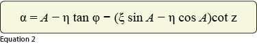
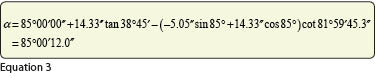
Additionally, the astronomic azimuth of the line is affected by the deflection of the vertical at the observing station. It can be reduced to a geodetic azimuth using Equation (2) where φ is the geodetic latitude of the observing station. Using the values given previously, the geodetic azimuth of a line with an astronomic azimuth of 85° is Equation (3).
Thus, the astronomic and geodetic azimuths for this line differ by 12″. The observed astronomic azimuth must also be corrected for the position of the instantaneous pole. However, this correction is so small that it is much less than observational errors typically.
Even though astronomic azimuths are seldom observed today, an angle, which is computed as the difference between two geodetic azimuths derived from a GNSS survey, will not exactly match what’s observed in the field. Since angles are simply the difference between foresight and backsight azimuths, the reduction of an observed astronomic azimuth to its geodetic equivalent is given by Equation (4) where ∠bif is the geodetic angle and ∠BIF is the observed (astronomical) value. 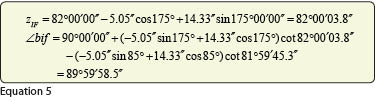
Notice that the largest correction term in Equation (2), which is η tan ϕ, is removed by differencing the foresight and backsight azimuths. Thus, this correction is often small.
As an example of this correction, assume that a horizontal angle of 90°00’00″with a foresight azimuth of 175°00’00” and a backsight azimuth, as before, of 85°00’00” was observed at the previously used station. To compute the geodetic angle, we must first correct the observed foresight zenith angle, which is also 82°. The equivalent geodetic angle for the observed angle is given in Equation (5).
 While the difference between the observed and geodetic azimuths is measurable, the difference in the observed and geodetic angle is small at −1.5″ and could easily be mistaken as an observational error. Obviously, the reduction of the observed astronomical angular values to their geodetic equivalent values is not going to make many surveyors rush to perform them. But these differences do exist, they can be large in some areas of the country, and they explain why some observations taken with conventional instruments do not match equivalent values from GNSS adjustment results.
Often the difference in geodetic and observed angles caused by deflection of the vertical is ignored. However, in some parts of the country this error can be measurable and significant. The same cannot be stated about the effect of convergence of the meridians on the azimuths of a traverse. Part 2 of this article looks at how convergence of the meridians affects azimuths in traverse computations and, more particularly, how it can cause what is apparently large angular misclosure errors in link traverses, which are becoming more common today since GNSS surveys can provide the necessary control at two distant locations. Additionally, I discuss the accuracies of geodetic azimuths that are typically listed in GNSS adjustment reports and why these azimuths should not be accepted as exact values.