Normally we create digital surface models (DSM) and elevation models (DEM) to analyze the topography and visual issues related to a project or issue. The requirement for accuracy and precision is paramount, ensuring that the correct method(s) of converting the data from raw source to an accurate model is more a work of art than scientific processing.
In recent years there has been a requirement for accurate landscapes and detailed terrains from the gaming industry. With more realistic games like Gears of War and Call of Duty has come a need for terrains which emulate the real world but are changed to make the game more exciting. It is interesting to know that GIS is being used more and more in gaming and cinema to create worlds which are uncannily similar to the world in which we live now.
How Is It Done?
There are predominantly two methods: taking a current landscape and altering it to match your requirement or creating something from scratch. The following steps show how easy it can be to alter a terrain using ArcGIS (with 3D or Spatial Analyst license0). This could also be done in GRASS, QGIS, or any one of the other geo-software out there.
For this example I will be using the Ordnance Survey Terrain50, a DEM with 50m cell spacing, and I am not going to run through creating a whole new fantasy landscape. Instead I will show how to change a small area to show how easy it can be to apply the method in your own model.
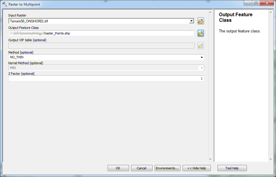
STEP 1: DEM TO POINTS
Using the geoprocessing tools, take your DEM (I have assumed it is raster as this is most common in my experience) and use the “raster to multipoint” tool.
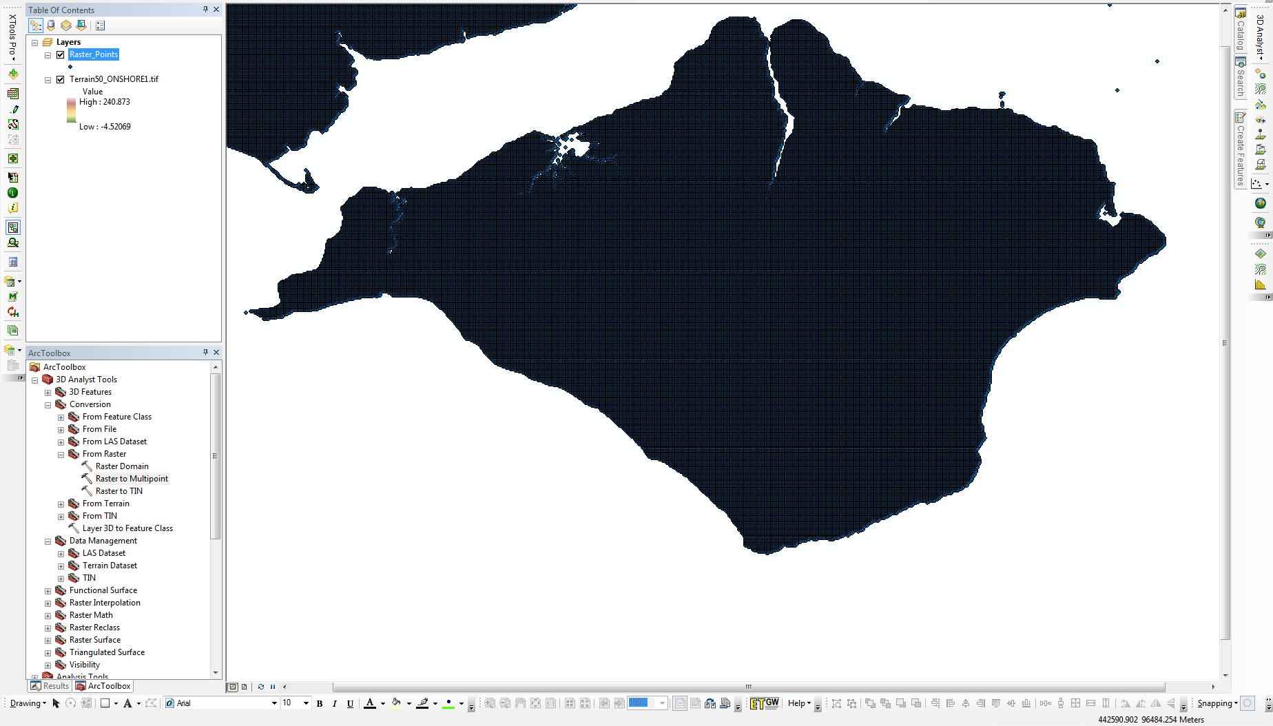
Once processed, you should have a set of points spaced at 50m:
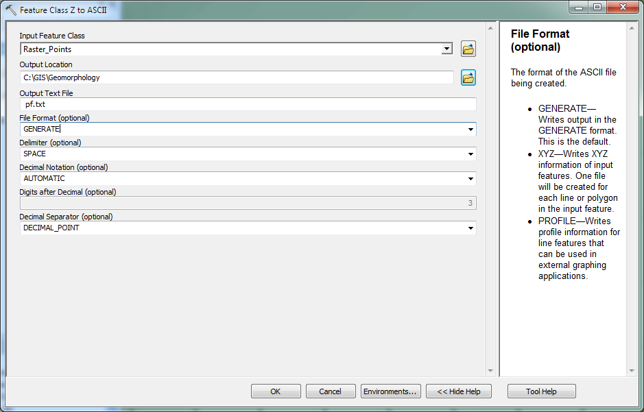
STEP 2: STRIP THE REDUNDANT INFORMATION
The next step is to change the data to a shapefile without all the extra information and in a single point format which can be finally interpolated back to a DEM raster.
We use the “multipoint to ASCII” tool to strip the data and convert it to a text file (CSV) which can be used.
STEP 3: CSV TO POINT
Now that we have stripped the data and have it back in a lovely XYZ or CSV format file, we need to convert it back to shapefile points (so that we can visually edit it). We could of course edit the data direct on the CSV file, but this tends to be a little more complex without visually seeing the location of the features we are altering.
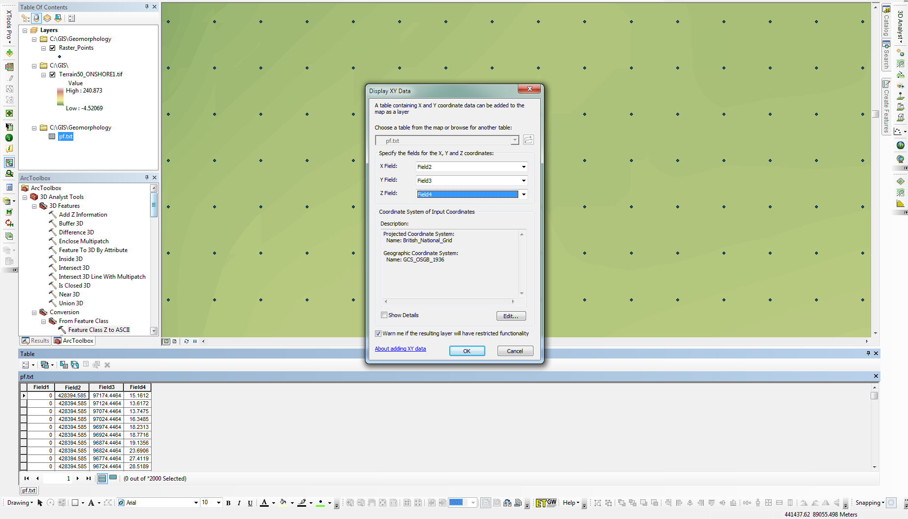
We now use the “Display XY” tool to create a virtual/temporary shapefile which we can use. The height (Z) field for this data is in Field 4.
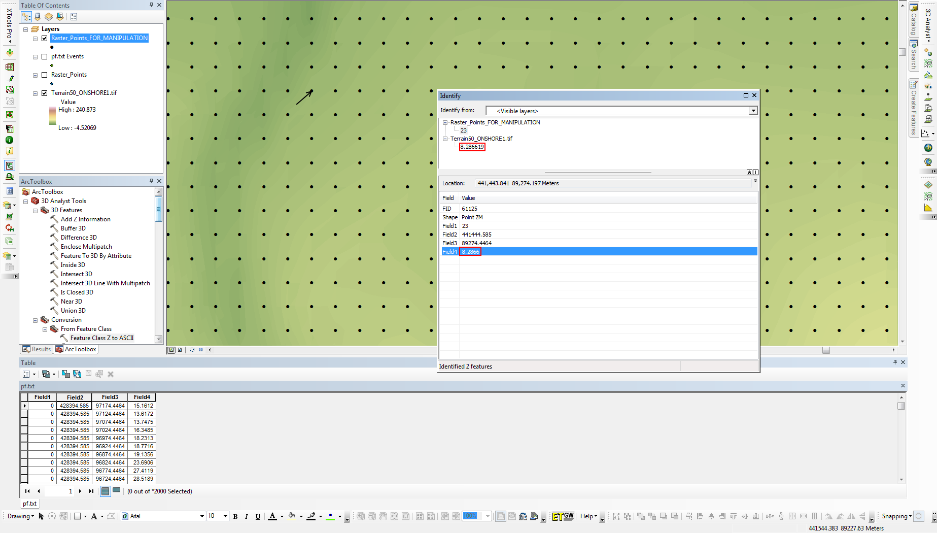
Once converted, do a quick sense check to ensure that the raster correctly matches the original raster it was based on (it should, though sometimes quirks happen).
STEP 4: START ALTERING THE LANDSCAPE
Now the fun part: we get to create our fantasy landscape. This can be done in a multitude of ways. One method is to edit the single points using the editor tool, or for larger areas the field calculator tool is good. So, as the field calculator is kryptonite to some, I’ll show how this was done on this model.
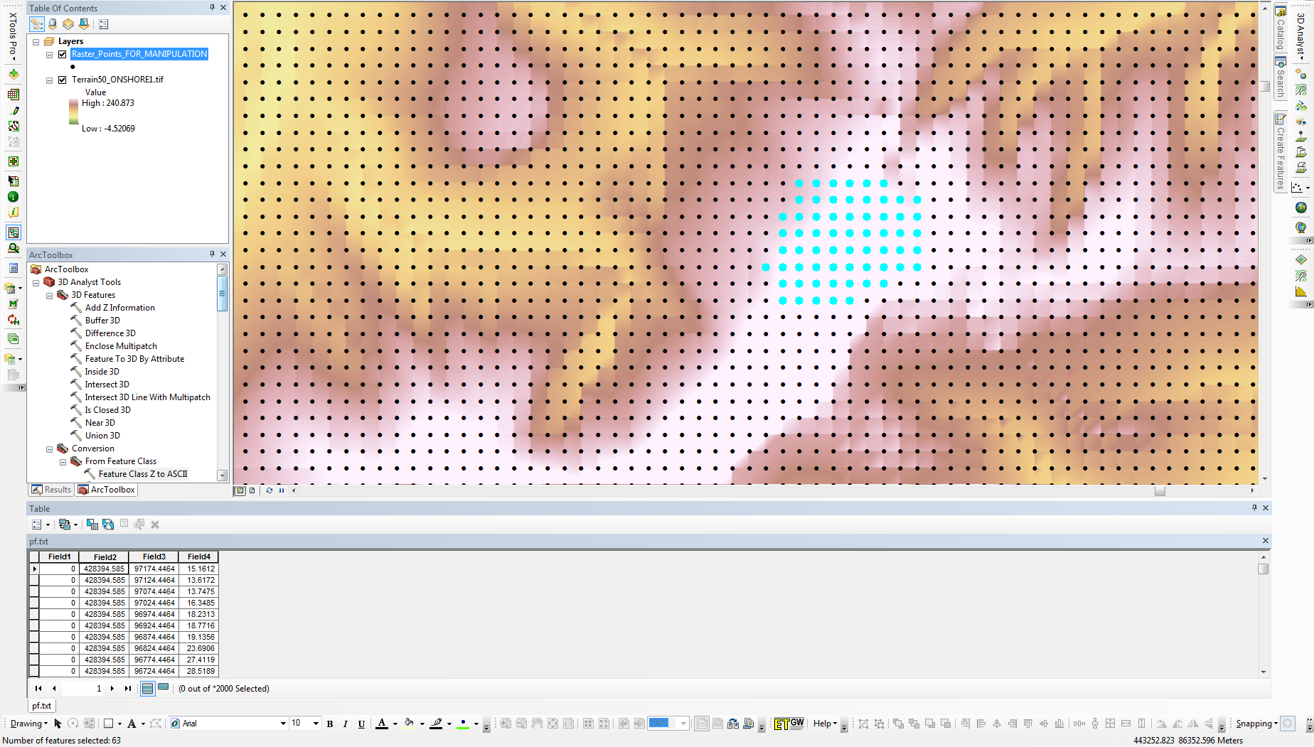
First select the points you wish to alter (shown in turquoise).
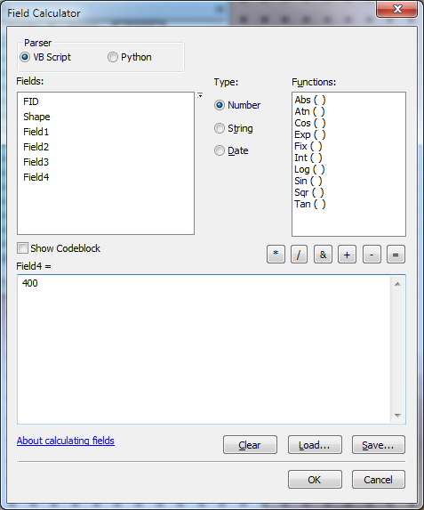
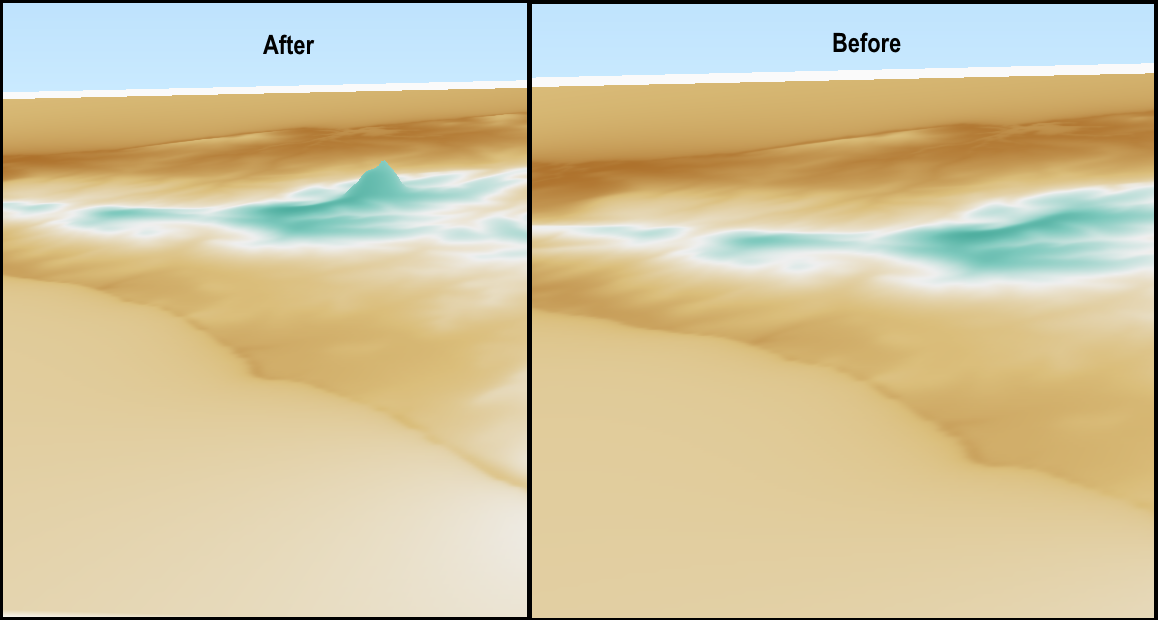
Next, open the field calculator and ensure that any options refer to editing ONLY the selected points (this was an option on earlier versions of ArcMap). The calculation is as easy as saying “I want Field 4 to equal 400” (remember which datum you are using!!) for this 400=400m. Below I have selected Field 4 and just put 400 in the query box.
All the selected points will now be 400m compared to the surrounding points.
Of course we can continue and create our work of art, using either guesstimation for something original or by analyzing and calculating the necessary factors to create an accurate representation of something from a book or image.
STEP 5: CREATE YOUR DEM
Now that we’ve altered our landscape we are going to interpolate the points to create a raster surface. As the points are regular spaced I’ll use inverse distance weighting (IDW). If you’ve added extra points and the spacing is irregular, you might find the kriging method works better.
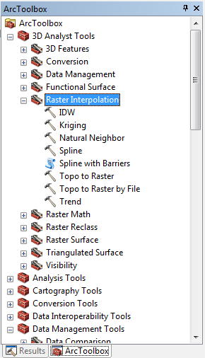
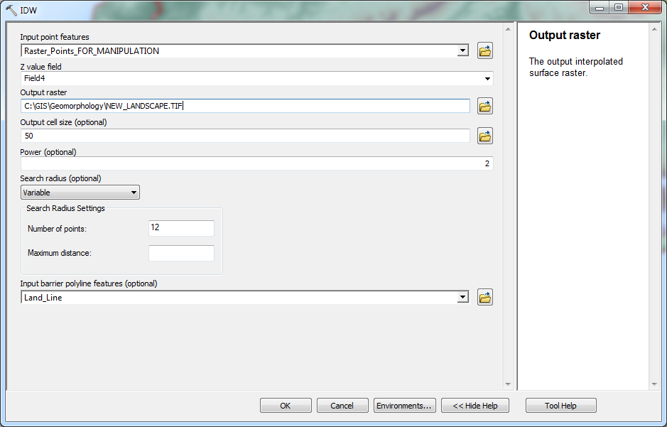
The left image shows where the interpolation tool(s) can be found and the right image shows the parameters which were used. Note that I am using a barrier polyline which surrounds only the Isle of Wight; this ensures that when the interpolation calculation is performed, that area outside of the required area is not considered. When interpolating coastal areas it is quite common to see “leaks” whereby features aren’t constrained and the tool hunts for the nearest point, creating false results.
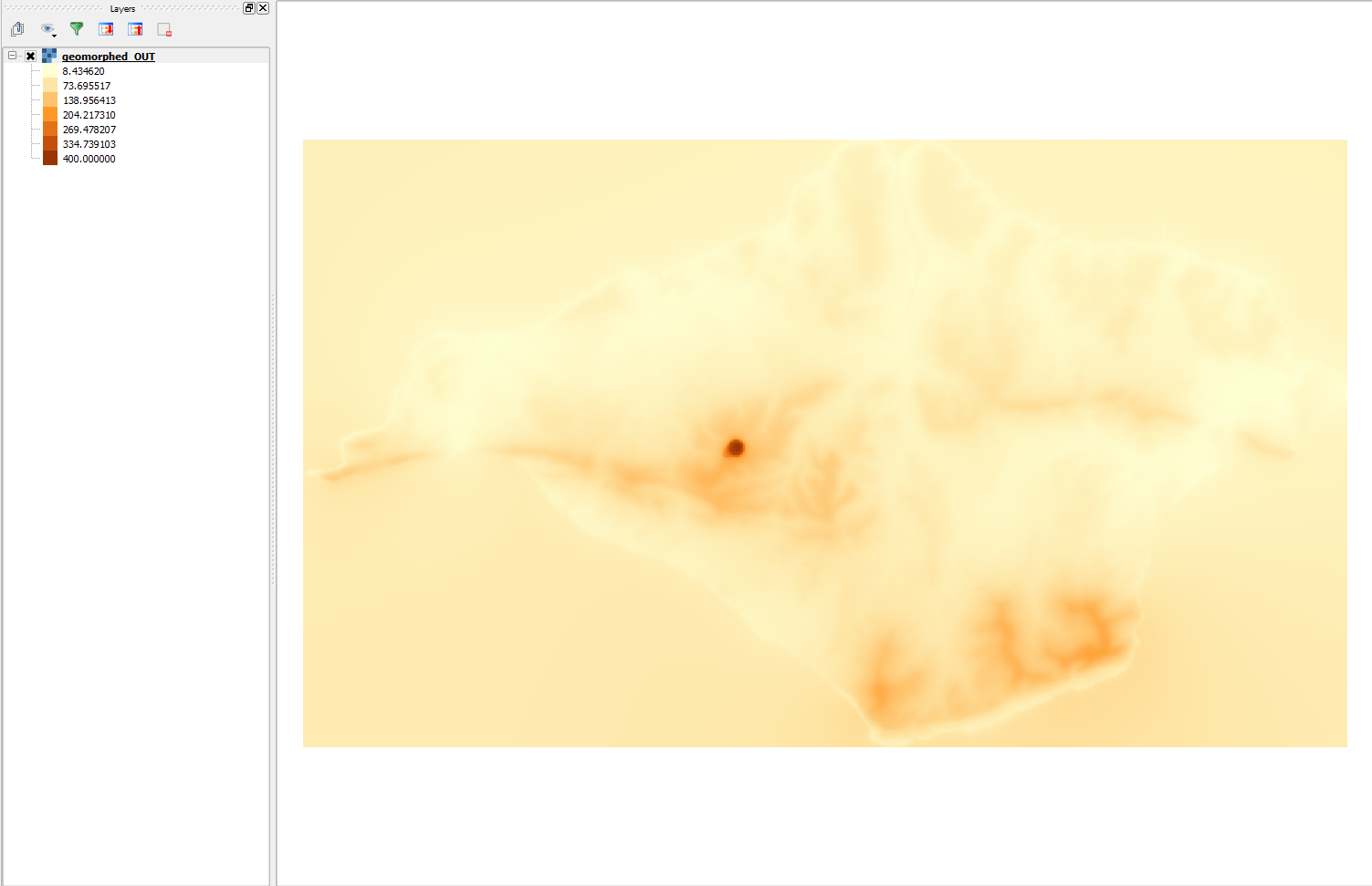
Once complete, you should have a new altered landscape at the same resolution as the original DEM. These altered landscapes can then be used in many 3D modelling software such as 3DS Max, Unity, and even (to a lesser extent) QGIS2Threejs.
But Wait—You Mentioned Another Method!
After running through this, you may be a little annoyed to learn that creating a fantasy landscape from scratch is relatively easy.
If you have an existing image, model or idea, draw it up as a contour map, and then digitize the contours. You could do this be drawing up the map on paper, scanning it, georeferencing it, and then using the georeferenced image to draw from, OR you could just draw straight onto the GIS.
Provide the correct heights to the contours and then use QGIS, GRASS, ArcMap (or any other 3D enabled GIS software) to convert the contours to DEM. I’m sorry, maybe I should have explained this method first.