A one-person crew provides foundational data for building a massive wind farm in Australia, using integrated survey technology.
When you look at the commanding stature and aesthetically pleasing symmetry of the turbine towers at the Mt Mercer Wind Farm in southeast Australia, it is easy to gloss over the central role that surveying and engineering played to build such a majestic site. From this perspective, the 64 wind turbines—towering 126 meters (413 feet) high and scattered across 2,600 hectares (6,400 acres) of green farmland—are a sensational and impressive feat of design and construction.
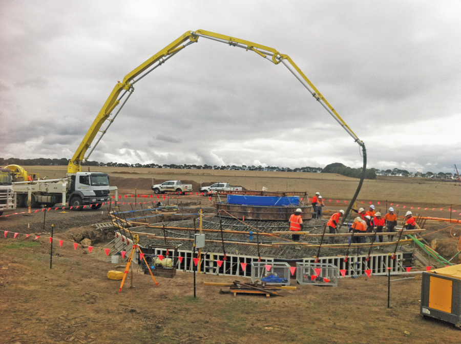
A Trimble S6 helps to monitor the embed section (wrapped in blue plastic) for any movement during the main concrete pour at wind turbine 33. About 330 cubic meters (430 cubic yards) of concrete is poured into the foundation in a single, continuous pour.
Weighing more than 200 tons, the turbine’s three tower sections (totaling 80 meters or 260 ft) are grounded by 4.5-meter-diameter (14.8-ft) steel and concrete foundations and are topped by the 69-ton nacelle, containing the gear box and generator. Each of its three blades is 45 m (148 ft) long, two-thirds the length of a 747’s wing. The hub and blades are assembled at ground level, then lifted into place by a crane in one single lift. It takes 1.5 days and a 50-person crew to assemble and erect each turbine.
Developed by Meridian Energy Australia, the A$260 million (U$S230 million) Mt Mercer Wind Farm is the second wind farm in the Victoria region and Meridian’s third wind farm construction project in Australia. Fully operational since September 2014, Mt Mercer’s turbines are forecast to generate enough energy to power almost 100,000 homes.
Building these big elements meant sweating a lot of small elements—the foundation layouts, the precise orientation of the hardstands, the precise position of bolt sets, and the precise location of tons of steel and concrete foundations—all set with precise survey measurements and control. All of that survey responsibility fell to TGM Group, an engineering, surveying, and planning consultancy with several offices in Western Victoria.
“With the complex nature of construction tasks and the size of the site, technological accuracy and mobility were key,” said Adam Criddle, a TGM survey manager based in Ballarat, 30 kilometers (19 miles) from Mt Mercer. “Using an integrated survey technology approach gave us the efficiency and flexibility to provide data solutions in real time for any given challenge on site, without losing data integrity, accuracy, or time.”
Despite torrential rains, temperatures ranging from below zero to scorching, a brush fire, and relentless dust and strong winds, TGM was able to provide the crucial survey detail upon which to build the Mt Mercer Wind Farm, and it covered 2,600 hectares of challenges, surprises, and resolutions … with a survey crew of one.
Manageable Vastness
TGM first blew into the wind farm market in 2007 when it was tapped to provide the linchpin survey data for the 128-turbine Waubra Wind Farm near Ballarat, the fourth largest in the country. It has since managed the survey work for two other wind farms in the Victoria region. Given its experience and strategic location near the chosen Mt Mercer site, Downer EDI, the engineering company responsible for the civil works, selected TGM in January 2013 to provide them with full survey support for all the construction aspects of the project.
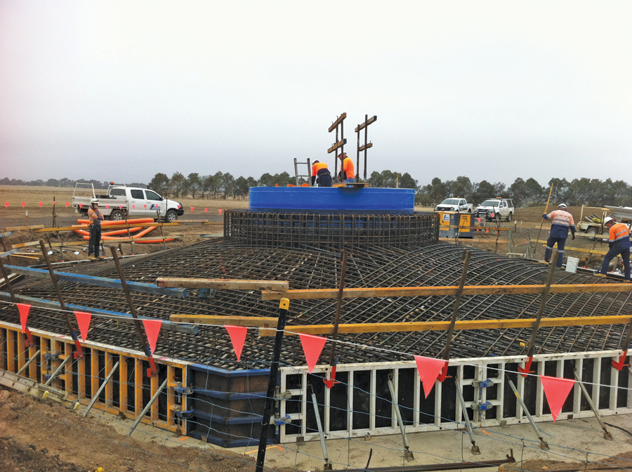
With the reinforced steel in position, crews perform a final inspection of turbine 33 prior to the concrete pour.
From the outset, the scale of the Mt Mercer site would present a considerable challenge. “The building site stretches across a 600-meter-high (1,968-ft) elevated plain with a high hill in the middle of it, creating a GPS communication shadow from one side to the other,” said Criddle.
“We not only had to ensure we could maintain accurate control and broadcast RTK corrections throughout the entire site effectively, but we also needed to have the adaptability to broadcast GPS formats that would be compatible with multiple survey brands and instruments in real time. The vastness of the project site would also require us to devise very efficient work strategies so we could quickly respond to the ebb and flow of Downer EDI’s survey needs in the field, while still meeting stringent precision requirements.”
What the vastness wouldn’t require, however, was an immense array of survey instruments and crew numbers to cover the space and volume of tasks. “The integrated survey capabilities of our equipment enables us to bring the massive job site down to manageable size,” said Nathan Farrell, TGM’s senior surveyor and lead surveyor for the Mt Mercer project.
“Its flexibility and functionality gives us the efficiency and mobility to quickly move from one end of the site to the other, employ the right instrument for any given task and instantly provide an accurate data solution with a few taps in the data controller. With that adaptability, we could fulfill our job assignments with a single-person crew, instantly handle any surprises, confidently provide quality measurements and help the project stay on schedule.”
Prepping for Hardstands
From the beginning, TGM’s primary focus was to provide detailed setouts for the turbine foundations and identify and lay out the best location for each turbine’s hardstand—the temporary work area for assembling and erecting the turbine components.
When Farrell arrived on site in February 2013, he sought a suitable spot to place his Trimble SPS880 GPS antenna, which would serve as a permanent base station and provide corrections across the entire site for RTK surveying with the Trimble R8 GNSS receiver.
With the control network established, the daily ritual then began of performing layouts and setting control points, positioning hardstand locations and turbine tower center points, placing grid lines, supporting machine-guided earthworks, laying out bolt sets, verifying field work, pouring concrete, and performing as-built surveys.

Senior surveyor Nathan
Farrell tasks the Trimble S8 and TSC3 controller at the Mt Mercer Wind Farm. TGM was able to provide all survey tasks with a one-person crew.
To accommodate the construction and erection of each wind turbine, each hardstand needed to be 45 m long and 25 m wide (the width of an Olympic-sized swimming pool) and maintain a crossfall gradient of exactly 5% to ensure proper drainage and safe operating conditions for the 750-ton high-lift cranes.
Excavated to a minimum of 300 mm (12 inches) below existing surface levels, each hardstand had to be back-filled with quarried stone and compacted to engineering specifications. Although the relative height of each hardstand varied for each turbine, to ensure the cranes could lift the turbine components into place, hardstands could never sit more than 2 m (7 ft) below the embed ring, the steel cylinder upon which the first turbine tower segment is bolted.
Based on pre-determined coordinates for each turbine foundation, Farrell used the R8 GNSS receiver and Trimble TSC3 data controller to collect a topographic survey of the area and locate existing control points around the hardstand location. Based on those points, he used the controller’s computation abilities to determine a balance plane that would both minimize earthworks volumes and provide the best position for the hardstand. That often meant Farrell had to recompute and amend the originally set hardstand orientations on the fly.
“As with most construction projects, plans change,” said Farrell. “So we had to adjust the previously planned hardstand locations as needed. The ability to consistently have RTK survey data within 10-millimeter accuracy and to run real-time calculations in the field allowed us to immediately and confidently deal with changes. Without that capability, we would’ve had to download and post-process all of our survey data each day to perform those same calculations. That is much more time-consuming and would have required a larger survey crew.”
Once the orientations and heights were approved, Farrell would stake out the hardstand locations and provide the design files to the earthworks teams, who excavated the hardstand locations according to the cut-and-fill design files. After the temporary worksite was backfilled and compacted, Farrell used a total station to perform a quality assurance survey on the hardstand to ensure the crossfall tolerances were in accordance with minimum/maximum clearances from the hardstand to the turbine embed.
To the crews’ credit, not one of the 64 hardstands failed to meet final QA inspection.
Preparing for the Towers
The below-ground preparations of the turbine foundations required the GNSS receiver and total station to work in concert, with the data controller as conductor. Similar to determining hardstands, Farrell used the R8 and TSC3 to stake out the turbine foundation locations and then supplied that design data to guide the excavation process by the earthworks contractors. Each foundation was unearthed to a depth of 2 meters.
Once the foundation had been excavated to the correct depth and shape, control grids needed to be established for the concrete crews to accurately place a flat, stable base layer of concrete, known as blinding, and to guide the subsequent layers of support grid beams, 40 tons of steel reinforcing, the embed tower section, and the concrete formboard.
To create the control grid, Farrell had to accurately position the center point of each tower. With the R8 receiver, he first established control within the excavated pit, confirmed the center point, and saved that to the data controller. He then placed the Trimble S6 total station over the center point and referenced a remote, existing reference point on Mt. Mercer to mark the grids to millimeter accuracy as required. To maintain the correct surface level as the blinding was poured, steel rods topped with yellow safety caps were placed as benchmarks.
From there, Farrell interchanged his GNSS and total station technologies to provide reference marks and grid lines and spot checks as the crews added each foundational layer. And with each new layer came increased scrutiny, particularly when crews reached the embed tower: the critical anchor of the turbine tower base.
As the 160-meter wind turbine rests on this steel and concrete cylinder stub, there was zero room for any positional errors in the horizontal or vertical plane; the embed ring had to be placed and remain within the construction tolerances of 5 mm horizontal (0.2 in) and 2 mm (0.08 in) vertical. That required a minimum of four as-built surveys, which Farrell performed using the Trimble S8 total station and a precise optical level.
“Having the total station precision and the data controller’s desktop computer functionality was really key for this phase,” said Farrell. “I could quickly reference the relevant control grid, use the S8 to automatically and accurately shoot specific points and verify the integrity of the embed ring in seconds. And during the main concrete pour, I could monitor the structure in real-time as well.”
About 330 cubic meters (10,594 cubic ft) of concrete is poured into the foundation (including the collar around the embed section) in a single, continuous pour. That much volume of material at one time could cause the ring to shift. To account for that risk, crews set the S6 on previously set external grid reference marks to monitor the embed ring for any significant movement horizontally or vertically during the main concrete pour. After the pour, Farrell completed a survey of eight points around the top of the embed to confirm if any movement had altered its position.
100 Bolt Sets
When detailed set-out and as-built data were required for the electrical substation foundation bolts and concrete formwork, Farrell brought in the Trimble S8 to capitalize on the instrument’s robotic functionality and high-precision EDM range.
A significant and critical part of Farrell’s cope was to precisely position more than 100 bolt sets, some of which contained eight-bolt configurations that were cast into the concrete footings. He used the S8 to set pins on grids to position the bolt lines, and once the steel was placed and the bolts were erected, he performed a check survey of all the bolt locations prior to the pour and adjusted any that were outside position tolerances. The slab was then poured, and Farrell confirmed the final position of the bolts in the concrete formwork.
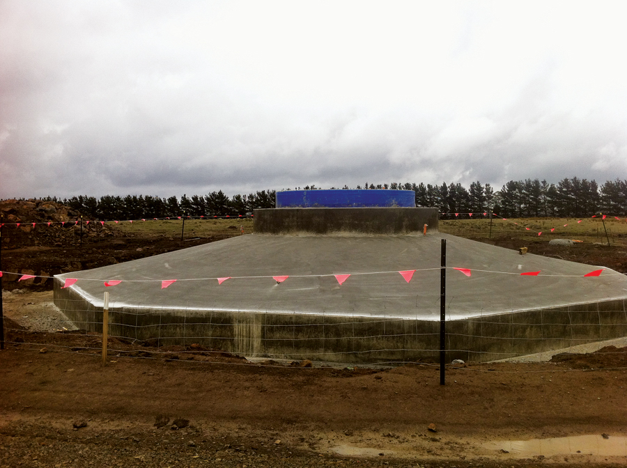
Wind turbine 2’s finished foundation. Still wrapped in protective blue plastic is the embed ring, the steel cylinder upon which the first turbine tower segment is bolted.
Performing this essential work without survey technology would have been significantly labor intensive and would have increased the potential for miscalculating control points to set the bolt lines, said Farrell.
“With the S8, I can lay out bolt patterns by simply inputting into the controller the point number for a specific bolt and the instrument automatically turns to where it should be,” he said. “Without that feature, I’d have to turn specific angles manually and manually input calculations to lay the features out. That’s really laborious and it leaves a lot of room for error.”
With the small foundational elements secured, crews could then complete constructing the electrical substation, using the watchful “eyes” of the survey equipment to ensure the accuracy of the build. Having that ability to accurately match the ebb and flow of myriad crews’ survey needs with fluid, integrated technology was a key enabler to help successfully move the Mt Mercer Wind Farm from the ground floor up, says Farrell.
“We couldn’t have engaged in a project of this scope without a reliable GPS unit,” he concludes. “Nor would we have been able to provide the accuracies required, as quickly as required, without precise total station technology. But the most significant advantage in the field was the ability to simultaneously run the R8 in conjunction with the total stations and seamlessly integrate and manage the data with one survey controller. That gave us the ability to run the whole show with one piece of equipment.”
This a show has now ended with the whirring turbines on display. And Farrell, his team, and their survey technology played a starring role.