A Florida surveying company puts a new technology to the test on an historic canal fronted by 21 subdivisions.
Editor’s note: The announcement of the Trimble V10 imaging rover in late 2013 was greeted with a mix of excitement and questions (“what is it?”). With close-range photogrammetry just beginning to reach the toolboxes of surveyors and mappers, the V10 spurred a rare in-house product review (see “V10, R10, RTX et al.” January 2014 Professional Surveyor) in which we expressed being “pleasantly shocked out of disbelief.” There appears to be a bright future for this type of technology, and readers asked for a follow-up case study.
GCY, Inc., a professional surveying and mapping firm headquartered in Palm City, Florida faced a large and unique contract. What became known as the “C-100A” contract, named after the prominent canal south of Miami (see sidebar on page 25), contained several components. The contract called for GCY to survey and locate the section corners and key cadastral points in the 21 subdivisions that front the canal. They would reconcile all of the subdivisions and descriptions and then set markers and develop a map of the canal right of way.
The company would also set second-order vertical control benchmarks and provide locations for 12 core borings needed for geotechnical analysis. In addition, GCY needed to provide locations of all improvements and planted landscaping in the right of way, in its adjoining maintenance easement, and within 10 feet of the easement. GCY would also survey the canal itself, providing a full-length profile at 25-foot intervals with cross sections extending beyond the maintenance easement.
Even the client, the South Florida Water Management District (SFWMD), realized it would not be an easy project. “It’s a challenging area for this type of surveying,” noted SFWMD surveying and mapping administrator Rick Barnes. “It’s all residential with a great deal of fences, improvements, and landscaping. There’s a huge number of things to locate and not a lot of room to work in.”
Rehabbing a Neighborhood Asset
The land south of Miami consists of a few inches of topsoil and soft reef rock on top of a layer of hard limestone roughly eight feet thick. Beneath the hard limestone is a layer of softer limestone. With the layers exposed by canal construction, over the years the water has eroded the softer rock and undermined the harder limestone. In some places, the hard limestone has sloughed into the canal.
The sloughing fills in the canal and reduces its ability to carry water. Additionally, sloughing is changing the shape of the canal, and Barnes wants to be sure that it’s not creeping out of its right of way. To solve the problem, the District is developing plans to rehabilitate the canal to bring it back to its original design.
To develop the rehabilitation plans, District engineers need detailed information on the C-100A canal itself and how it relates to the properties that lie along its path. To gather the information, Barnes turned to GCY, Inc. According to GCY president George (Chappy) Young, GCY has provided surveying services to the District for more than 20 years under a series of competitive contracts. For the work on the C-100A, GCY’s contract extended for 3.8 miles and covered the northern portion of the canal.
Calm Waters and Needed Repairs
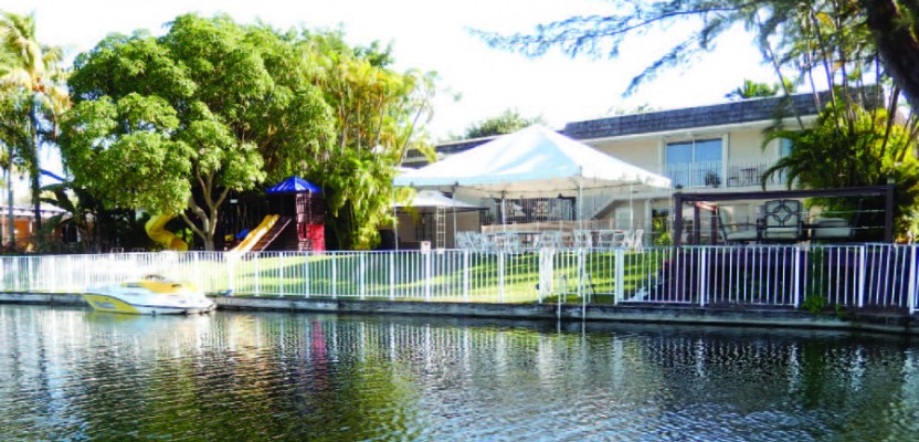
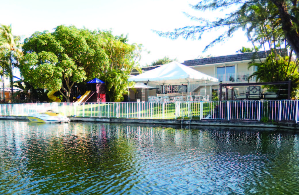
Weaving through the Miami suburbs, the Cutler Drain canal system is part of the area’s south Florida way of life. The calm waters run
In a scene repeated hundreds of times, homeowner improvements abut the C-100A canal. The survey would determine how neighborhood improvements related to the canal’s right of way and maintenance easement.
through dozens of neighborhoods and include two small lakes. For nearly five decades, the Cutler’s canals have been part of the landscape for thousands of south Miami residents. Today it’s in need of repair.
Built in the 1960s by the U.S. Army Corps of Engineers (USACE), the Cutler carries water from the south Miami suburbs into Biscayne Bay. After construction, USACE turned the Cutler canals over to the SFWMD, where they became part of the District’s efforts in managing water resources in southern Florida. Covering 16 counties from Orlando to the Florida Keys, SFWMD serves nearly eight million residents. The Cutler Drain is made up of several individual canals and includes 13.5 miles of navigable waterways that support fishing and small boats. One of the canals, the C-100A, provides drainage for the villages of Pinecrest and Palmetto Bay.
Construction of the C-100A came during a period of rapid development in south Florida. According to SFWMD surveying and mapping administrator Rick Barnes, roughly 20% of the subdivisions along the canal were platted prior to canal construction. By the end of canal construction in 1967, 50% of the lots along the canal had been developed. The canal right of way appears on all of the subdivision plats for the area. Today the C-100A canal runs through mature neighborhoods and complements backyard landscaping in hundreds of single-family homes. But the canal is showing its age and the effects of the region’s geology.
Combining Technologies and Data
Young and GCY vice president Pete Andersen recognized that to produce the deliverables, the project would require the use of multiple measurement technologies together with the ability to combine the different types of data. To measure the canal profiles and data for cross sections, GCY used a small boat equipped with multibeam sonar. Side-scan sonar enabled the crews to measure areas of undercut where the soft limestone had eroded beneath the harder upper layers. In addition to the sonar, crews needed to then manually probe the profile every 25 feet. If they encountered silt or loose sediment on the bottom, they would probe down through it in an attempt to locate what might be the original cut.
Things got even more interesting in planning for the work on land. Most of the positioning used GNSS. Using a Trimble R10 GNSS receiver connected to the Trimble VRSNow service operating in the area, the GCY crews could capture positions on section corners and cadastral control points. They could also use GNSS for locating improvements in the more than 250 residential back yards along the canal. But the limited access (the canal is surrounded by private property) and sheer volume of information encouraged them to look for a faster approach.
As they were planning the work in late 2013, Young and Andersen learned about the Trimble V10 imaging rover. They decided that it could help speed up the work. The V10 works by capturing 360° panoramic images that can be used to precisely measure the surrounding environment. While it can be used alone, GCY opted to integrate the V10 with a Trimble R10 GNSS receiver mounted on top. Alternatively, they could mount a prism atop the imaging rover to capture the rover’s position with a total station. GCY crews could collect multiple panoramas to be processed using photogrammetry functionality built into Trimble Business Center (TBC) software.
“It seemed like it would be a good fit,” Young said. “The Trimble V10 equipment utilized in that environment could reduce our field labor time.” Because the project was a two-hour drive from GCY headquarters in Palm City, the field costs included hourly costs plus expenses for per diem and out-of-town housing. “So any time we can reduce our field labor cost—even at the expense of possibly increasing the time in the office—the comparison is an advantage,” Young said. Eager to put the new technology to work, Young ordered one of the first V10 production units. By mid-January 2014, their new equipment was in hand.
Observing, Adjusting, and Delivering
GCY assigned two crews to the field work, laying out a week’s work at a time to collect data in successive back yards. The crews moved
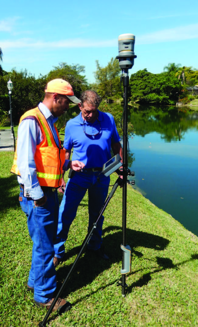
Lucas Young and Rick Barnes review an image captured by the Trimble V10. The system provided significant reduction
in field time.from one back yard to the next locating all the improvements. They soon learned that the imaging rover could radically quicken the work. Rather than collecting individual points using RTK, the crews could shoot photographs from a few locations.
The Trimble R10 atop the V10 imaging rover captured an RTK position for each photo station and automatically attached the images to the point. Because the V10 uses the same field software and workflow as Trimble GNSS and total stations, images could be captured with no additional time or steps. The crew could view the panoramic photos using the tablet mounted on the pole. Without the need to walk to each object, they could complete a backyard in minutes. “When we did our estimate on the location of improvements, we figured it would take nearly two hours per lot per crew,” Young said. “But it turned out to be more like 20 minutes per lot.”
At the end of each week, the crews returned to Palm City and downloaded their data to the TBC computer. The field crews used a separate file for each backyard, and the GCY office team received 40 to 50 files each week. GCY senior CAD technician John Yancy used TBC to automatically detect and generate tie points, which are points that appear in multiple panoramas and are used to register multiple photos into a single model.
The crews typically took between 4 and 12 panoramic photos or “photo stations” per lot. The software would search for features that would work well as common tie points; edges of walls and window corners are commonly found, but Yancy was surprised by some of the other features that also seemed to work well, like branches and leaves of hedges, or sharp tips in stucco.
To ensure that there would be good tie points for each lot, the crews drove in lath with the Day-Glo orange paint on the tops. These showed up well even in areas of shadow. The entire process was a learning experience, but the learning curve did not impede rapid completion.
With the photo stations held to the VRS-derived coordinates and the photos tied, Yancy could “survey in the office” to develop coordinates for points, lines, and polygons. Descriptors for the individual improvements were assigned from the same feature code library used by the field crews.
“We drop the points into our base drawing,” Andersen said. “Then we start connecting dots based on the field notes and what they see on the underlying aerial photography.” Considering the often thick and varied vegetation, the team had expected to need to fall back to conventional methods far more often than they did. The V10 had exceeded expectations.
Managing the Learning Curve
GCY quickly learned that—as with any new technology—there would be limitations. In some locations, dense tree canopy made RTK impractical, so the crews would set intervisible points in an area with RTK coverage, returning later with a total station to collect the detailed data. They also learned the nuances of the imaging system. Thick vegetation introduced challenges in visibility and lighting, which sometimes affected the ability to automatically identify tie points.
In the first few data sets, GCY used the manual tie points workflow in TBC to identify about 25% of the tie points. After consulting with Trimble, they modified their field workflows to capture photo-observable backsights and check shots to more quickly process the data and create deliverables in the office. “Some of the difficulty came with the terrain,” Andersen said. “Things are so close—houses no more than 20 feet away—and there might be vegetation between the lots. So we worked in a confined space, and because of this we often needed to create manual tie points.”
The teams also became adept at spotting areas where they needed to capture additional images. In some locations, the crew made the assessment as to whether or not a particular back yard was suitable for the V10. “There are probably 20 yards that the crews decided to skip,” Young explained, “and there were others that we couldn’t resolve in the office. In those cases we would move on and come back later with the total station.”
To check the accuracy of their work, the GCY teams measured check points that would be easy to identify in the photos. The accuracy of the photo-derived points consistently met the project requirements. Young noted that specific accuracy could vary based on the geometry of vectors in a model as well as the distances from the camera to an object.
In two months of work, the two crews collected roughly 98% of the needed information. As the fieldwork for locations wound down, the crews filled in missing data and completed cleanup and checking on the improvement locations. After that, they started work using the imaging rover to set points marking the canal right of way.
In the office, the work advanced to combining the sonar data with points on land to produce drawings of the canal right of way, profiles, and cross sections. GCY needed to prepare an assortment of documents for the District. Hardcopy deliverables included copies of the survey and cross sections as well as cadastral monument records. GCY also delivered softcopy CAD files for the District’s AutoCAD system and PDF files of the survey documentation. The District will use the files to model the canal and identify and prioritize locations where rehabilitation is needed.
It’s likely that rehabilitation work on the canal will affect the surrounding property. To protect the interests of the District and homeowners, Young and Andersen needed to ensure accurate survey results. The varying widths of the canal, as well as its right of way and easements, required significant attention to detail, and GCY was diligent in double checking all results.
GCY was also proactive in keeping homeowners advised of their work. They alerted local law enforcement about their work and developed flyers to hand out to owners and hang on the doors and gates of all property they accessed. The flyers notified the owners that their property had been surveyed and gave Young’s contact information if the owners wanted to discuss any concerns. Out of 250 landowners along the project, Young said that only two were uncooperative.
New Roles for Imaging
Even before the work wound down on the C- 100A, Young and Andersen began to identify new projects for their V10. Much of the firm’s work is cadastral surveying, and they have developed proposals for ALTA surveys on commercial sites. “I think it would be perfect for that sort of thing,” Andersen said. “I could see it being a great advantage on an ALTA survey for a shopping center.” During the C-100A project they conducted some improvement surveys that would have benefitted from the V10. But the instrument was too busy on the canal to jump to the other jobs.
Andersen thinks the imaging rover can replace conventional techniques in unexpected ways. He described using imaging technology for measuring concrete forms prior to pouring. The measurements, required to verify the proper location and elevation of the forms, are usually made using a total station and differential level. The fieldwork can take considerable time. “We think we can use the V10 to do it in a couple of minutes,” Andersen said.
Young is proud of his company’s ability to invest in new technologies. He said that as a new technology comes along he looks at it to compare potential productivity gains to the cost of the equipment. Young has invested in new technology many times in the past, and not every investment has paid off. But he’s confident that their investment in the V10 will turn out well. While the savings in field time are somewhat offset by increased work in the office, the technology has already produced a significant net gain. And the ability to use photos to measure additional features without returning to the field will provide long-term benefits.
Young compared the Trimble V10 with his company’s past investments in early GPS systems. “There’s an advantage to each acquisition,” he said. “You can’t be afraid of investing in innovation and new technology. Looking at the dollar investment in the V10 and what it’s already done for us, it’s been a no-brainer.”