A visit to Trimble’s engineering and production center in Danderyd, Sweden, reveals the story of the SX10’s development.

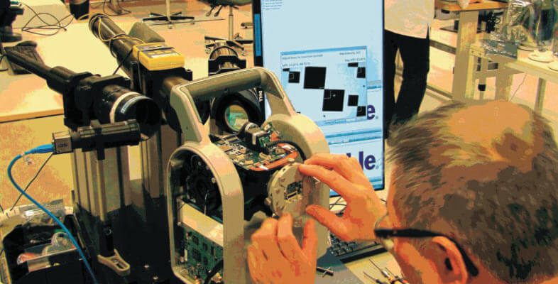
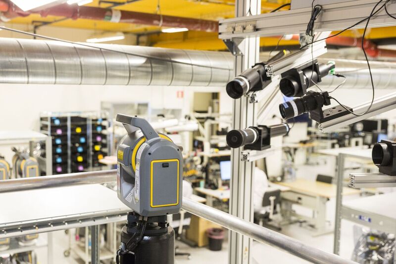
Total stations, scanners, and the new SX10 are engineered, assembled, and tested at the newly refurbished Danderyd facility. Each instrument progresses through dozens of assembly, adjustment, and test stations. Manufacturing technicians rotate assembly and test stations daily, with complete trace-ability of all data for each individual instrument stored in a database. Credit: Schrock.
As surveyors, we purchase and use some of the most sophisticated instruments of any field-oriented profession. Such sophistication yields incredible precision, accuracy, reliability, and flexibility, and, as would be expected, can carry hefty price tags. With such purchases, we gain ownership of the physical instruments, but there is a deeper form of ownership to be gained. By knowing more about where your instruments come from, who designed them, and the science behind their design, you become a stakeholder in the development cycle—and a peer in a community of users.
Among the most popular features we at xyHt have had the honor of publishing are factory tours and visits to the engineering centers for various manufacturers. Hearing directly from the developers and manufacturing engineers provides a whole new level of perspective and appreciation of the technological wonders they spend many years perfecting for us. Contrary to a popular misconception, the developers do not want us to view these instruments as a “black box.”
They are adamant about this: they want you to know more about what goes on inside. Almost without exception, developers are eager to help inform you of the inner workings (except certain elements to protect an edge in the marketplace). More-informed users make for better users, and more-skilled users push these instruments to their full potential. This bolsters a reputation for excellence and provides feedback; users become better partners in ongoing development.
I had been planning to visit the famed Danderyd, Sweden, facility of Trimble for several years. As a user of many types (and brands) of instruments over the years (including geodimeter and current Trimble total stations that originate from Danderyd), I considered this definitely a bucket list item. When I talk to users they say they are not really sure where their various Trimble instruments are manufactured; in fact, I hear responses like “Japan? China? California?”
The answer is that they are engineered, developed, and manufactured in many locations, and through international teamwork involving multiple facilities. For example, the “S” series of Trimble’s robotic instruments, and more, are produced in Sweden and have been as part of a legacy of related companies going back more than seven decades.
Last summer I was informed that my visit would need to be delayed; the factory was being expanded, modernized, and refitted (presumably for new rumored products). We now know that this activity was centered around the development of the new SX10 scanning total station that was announced at the INTERGEO 2016 conference and trade fair (Hamburg, September 2016). My visit finally came in March 2017.
The following story is really about the development and manufacturing team and their dedication in producing these sophisticated solutions, featuring their latest creation, and a factory tour as a backdrop. The SX10 is a significant development, a worthy example of the fine work going on at the Danderyd facility.
Behind the Big Eye
There is a lot going on behind that distinctive large lens on the front of the SX10, a lot more than meets the eye. And there is a lot going on inside the utilitarian yet not unpleasant “Swedish industrial style” walls of the Trimble facility in the small town of Danderyd, just a few rail-stops north of Stockholm. Here is where most of Trimble’s optical instruments are designed, engineered and manufactured. This includes robotic total stations, scanners, and now the SX10, an instrument platform that was such a departure from existing designs that much of the recent modernization and expansion of the facility was done to accommodate its manufacture.
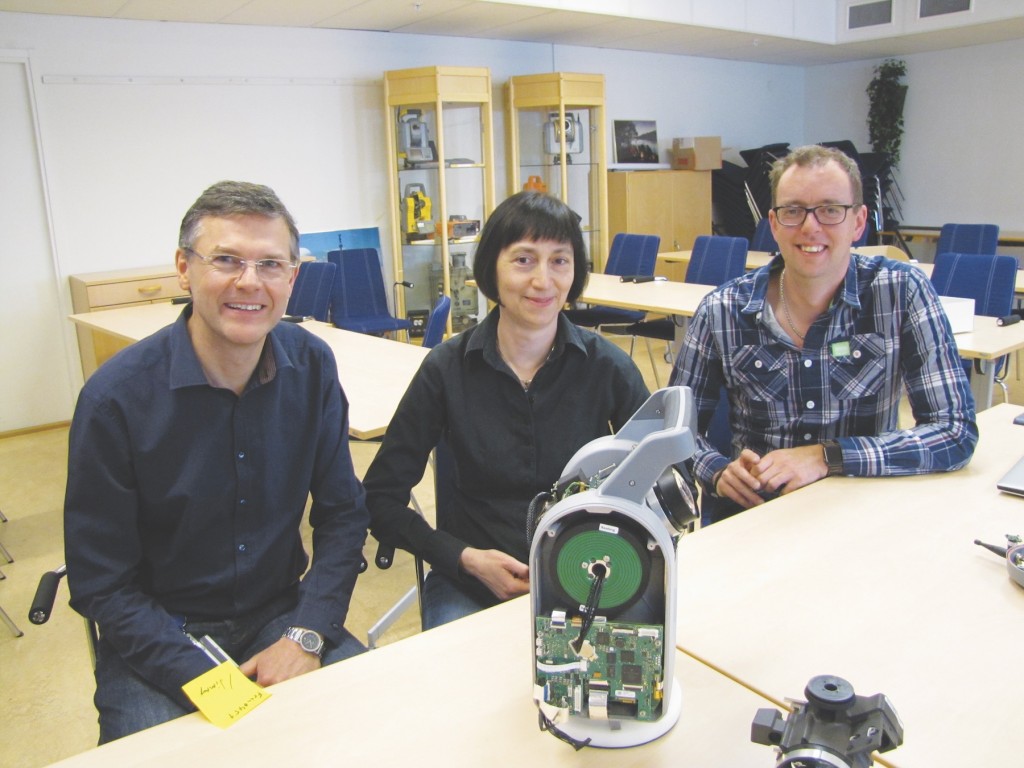
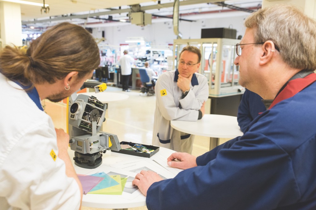
Left to right: Christian Grässer R&D specialist, Stella Einarsson system project manager for the SX10, and Mikael Nordenfelt R&D Specialist interviewed for this article. In the background: This meeting/training room also featured a mini-museum of noteworthy AGA/Geotronics/Trimble instruments. Credit: Schrock.
“We really wanted to make the best total station in the world,” said Stella Einarsson, system project manager for the SX10. The SX10 would tax the R&D skills and resources of the engineers and scientists in Danderyd, working as part of the global team that would bring this bold idea to fruition. Danderyd is part of a scientific, R&D, and instrument production lineage that spans more than a century and has garnered many “firsts and bests.” (See the section below: d=vt.)
It is fair to emphasize how significant a departure from legacy instruments this new solution is, not only for the AGA-Geotronics-Spectra-Trimble lineage, but for the industry. The SX10 was not based on an existing platform. Nearly every component had to be developed from scratch: from foundation science, on up through completely new manufacturing engineering, production processes and testing elements.
Like many surveyors, I had seen the recent press, videos, and ads about the SX10, seen it in action, and shared many a conversation with other surveyors, a mix of excitement and the kind of guarded skepticism common when we see something new. Actually, when the first ads were released some folks dubbed it the “bug-eyed monster” and wondered if it was a new scanner or a new total station; even the developers wondered how to characterize it.
After the team at Danderyd showed me the inner workings and how it is engineered and explained what they went through to make all of the elements work together, I had no qualms at all about insisting this be a cover story. This is not just another total station with some “extras”; this is in some respects an exceptional total station that also adds scanning and imaging capabilities in a manner not yet seen in the industry.
How different? I would soon find out during the factory tour (and taking the instrument for a spin), but first there was an opportunity to meet some of the team and hear about the history of the culture of precision they work in.
Dr. Erik Bergstrand
d=vt
Distance equals velocity multiplied by time. [Note that the equations for terrestrial electronic distance measurement are much more complex, involving deceleration, constants, effects of atmospherics, and more, but the roots are in Newton’s laws.]
In 1941 scientist Erik Bergstrand, with the Geographical Survey of Sweden, had been trying to find a way to better determine the speed of light. He conceived of a system of electronically controlling light pulses as opposed to mechanical slotted wheels. By 1947 he had working prototypes that could transmit 10 million light pulses per second to a mirror over 30km distant, and by calculating the total transit time out and back the results could be computed to nearest millimeter.
By the time Bergstrand had published his doctoral thesis, “A determination of the velocity of light,” results with his prototypes were so promising that AGA (Aktiebolaget Svenska Gasaccumulator, a state founded scientific, energy, and industrial company) was backing his development of the first commercial electronic distance measurement devices (EDM). AGA purchased his patent and continued development of his geodimeter (GEOdetic Distance METER).
By the time the Geodimeter 1 was released in 1953, the instrument was viable to be used in the field for geodetic measurements. While bulky by today’s standards, with 30cm mirrors, it also needed an external generator, and with a premium on training and computation, the device and subsequent versions was acquired by scientific, geodetic, military, and commercial entities all over the world.
But the advent of “instant distance” was still years in the making. The model 2 in 1955 required 45 minutes of observations and weighed 170kg, but with a range of 50km the utility for long-range precise measurement (when compared to any legacy analog method) made these instruments a godsend for geodesists and surveyors.
What would follow was rapid progression in EDM development—refinements, different frequencies, lamps—by model 6 in 1964, it was completely transistorized and utilized lightweight rechargeable batteries. 1971 saw the first of what we now call “total stations”: adding precise distance ranging to theodolites (with data stored on punch paper). In 1973 Geotronics became an independent company from AGA.
Highlights in the Geodimeter line to follow include the 1978 Geodimeter 120 (the “Semi-Total Station, automatically computing horizontal distance). The Geodat 122 handheld peripheral was added the same year to record measurements, later enhanced in the Geodat 126 model with the computing power of the HP41 scientific calculator.
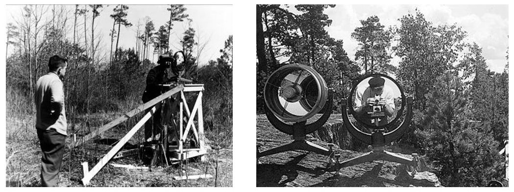
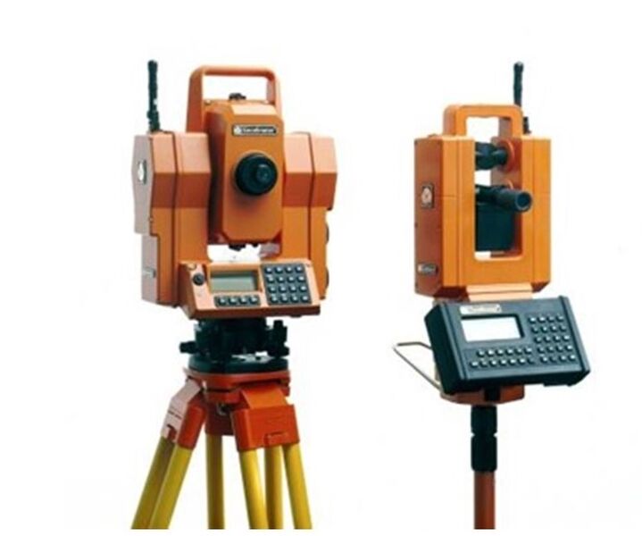
Geodimeter Model 1 (left) and reflectors (right) – circa 1953. Credit: Trimble.
In 1986, the third generation of total station had arrived: the Geodimeter 440 was the first total station with on-board programs, and this was also the form factor users would become familiar with for decades to follow. 1990s Geodimeter 460 was servo driven, and that same year the 4000 was released—the first robotic total station—control radios linked to an operator carrying the rod. Coaxial EDMs would be added, then the Geodat Win (first maps on a controller), and long-range reflectorless (DR) in 2000.
But there were other changes ahead for this lineage, and that came in the form of another pioneering company, one that had its roots in the rapidly developing field of global positioning systems.
Geodimeter 4000, the first robotic total station – circa 1990. Credit: Trimble.
In a development trajectory, like that which Dr. Bergstrand sparked for EDMs, the 1978 founding of Trimble by Charlie Trimble and three partners brought commercial viability to high-precision GPS instrumentation. Read more about the founding of Trimble in our interview with Charlie Trimble. Several steps led to a convergence of these pioneering high-precision optical and satellite-based solution providers. By 1981 the electro-mechanical companies of the AGA group formed in Sweden under the name Pharos, which would subsequently buy the U.S. company Spectra-Physics. Later incorporating Geotronics, the company would form a new company under the familiar name Spectra Precision. In 2000, Trimble purchased Spectra Precision, bringing the two worlds together.
The combined resources of these companies comprised a global team for R&D, hardware manufacturing, and software development. The team would continue to develop the optical line, introducing the next era of total station in 2005 with the “S” series. The advent and popularity of two other technologies—viable high-speed laser scanners and terrestrial digital imaging for surveying and mapping—sparked the development of the Trimble VX in 2007. The VX was a mag-drive total station that added digital imaging and rudimentary scanning capabilities. But by 2007 something much bolder was already cooking in Danderyd Sweden.

Technology, Teamwork, and Tenacity
Stella Einarsson has been at the helm of the development of the SX10 since its initial conceptual stage. “[Ours] is a truly international company,” she said. “The SX10 development team is spread out around the world, the hardware is centered in Sweden and Germany, field software is developed in New Zealand, office software [Trimble Business Center] in the U.S., and scanning software in France. The development teams cooperate in a really good manner to make everything come together.”
She said the global team works so seamlessly that it often does not feel like people are in different countries and time zones. “That is the power of this company: people are networking on the human level. Everybody’s focus is to serve our markets in surveying, engineering, and construction.”
“Total stations are complex by their very nature,” said Einarsson, “and in the same manner [the encompassing] R&D requires a high level of competence and education. We have many in the team with masters of Science or PhDs.”
Christian Glässer, an R&D engineer, said, “Roughly 300 people work at the Danderyd facility, and, at times, there are even more working in the facility. During certain periods, we have people coming from around the world. And we have market acceptance teams visiting for some very intensive test weeks.”
While the demands may be high, Einarsson and her colleagues thrive with the challenge. Said Einarsson, “The culture has been that our people truly enjoy working here, they like the products, and are extremely proud of the products—and they stay!”
Robert Jung, technical product manager, outlined the types of products developed and produced at the Danderyd facility (which had moved from the original AGA site 20 miles away in 1978), “The SX10, S5, S7, S9, the SPS [total station series] for construction and machine control, and RTS [total station] series for building models [BIM]—all based on the same S series.”
Scanners are also produced in Danderyd. Said Jung, “We produce the TX8 and TX6 in house and also some control units and targets.”
Sally
Einarsson said, “The SX10 development, also known as project Sally, has been a huge project for us. A fantastic level of cooperation is really needed to get this type of complex product industrialized and possible to produce.”
Where did the name Sally come from? It seems that R&D projects are given code names by Trimble management.
“At that time names of cars were being given,” said Einarsson. “The name was Mustang, so it became Mustang Sally and ultimately just Sally.”
Einarsson had run the project from the start to the very end as project manager. Mikael Nordenfelt, R&D specialist, has been with the project from the beginning as well, or as he said, “Long before it was a project. The general idea was not mine, but I did the first proof of concept to see if this idea would work from the beginning.”
Einarsson related an anecdote that when Nordenfelt and team was testing very early prototypes in the hallways of the office section of the facility she had to keep the door to her office open to add add extra distance to one of the test setups.
What prompted the project? Einarsson explained, “Starting about 10 years ago, scanners were still for early adopters; the technology was rapidly evolving, new things each year, new flavors. The focus in scanner development was always [about] faster and denser point quality. Trimble was producing and developing scanners at the time as well, like the GX.”
Trimble was undertaking what Einarsson calls, “product development on all axis. Mechanical total stations, high-end S [series] total stations, [GNSS], and the VX, which had imaging and scanning. The trend at the time [circa 2010] was towards small, fast, and inexpensive scanners; everyone in the industry was revisiting their product portfolio.” This only reinforced the reasoning behind the inception of project Sally, already underway.
The question facing Einarsson and the researchers and developers was, “Is there a way to combine the speed of a scanner with the accuracy of a total station? Would it be possible at all?”
Nodding and Spinning
The developers first sought what could be done by adapting and expanding the capabilities of existing designs.
The Trimble VX, introduced in 2007, was based on a high-end mag drive total station platform; it included the imaging capabilities of the S series (for documentation and terrestrial photogrammetry), but also the ability to shoot dense patterns of points in an array. The “scanning” was achieved by having the telescope unit of the total station kind of “nod” up and down as it panned across the field of view. The “scan” function was quite limited compared to dedicated scanners, but the VX found success and demonstrated that these additional functions could be useful in surveying workflows. Other manufacturers would employ the nodding concept as well, and while there have been admirable gains in speed (but with only to a range of about 1,000 points per second) none have achieved the levels desired for the SX10.
The “million points per second” high-end scanners typically employ spinning reflectors spraying shots along vertical paths while the entire instrument rotates on its horizontal axis to produce full or partial point clouds. Some capture full-color images for use separately for visualization or to create full-color point clouds. This can generate a lot of heat (which requires cooling systems) and use a lot of power, and instruments are often bulky and heavy, plus there may only be rudimentary traversing capabilities to connect the scanners’ station setups together.
So, to combine the two, which path should the team take? Start on a scanner platform and add total station capabilities? Or take a total station platform and add scanning? Einarsson, Grässer, and Nordenfelt spoke at length about how the school of thought changed back and forth, and how many concepts were tried using existing elements and concepts.
I was shown a video clip of a test using the fast (but not fast enough for scanning) mag drive of an S series total station, spinning furiously to create the scan “dome” as the telescope assembly incremented vertically. Calculations indicated that a “full-dome” scan in this manner would take many hours. That was obviously not going to work.
From many form factors considered, two emerged as front runners. One was taller to accommodate cooling elements and a possible spinning telescope unit, and another shorter and more like the final design.
“It needed to have a smaller form factor than originally planned,” said Einarsson. “It started as more of a scanner product than a total station. [Our] industrial designers gave us the much lighter version; but it also needed low power consumption and had to be able to dissipate heat. And high-quality measurements were needed as well for the traditional surveying markets—that was the vision. We wanted to have our cake and eat it too.”
How? Nordenfelt answered, “We could get away with this if we designed a completely new EDM style.” The team was about to boldly go forward.
By about 2010 the idea of making it either scanner-centric or total station-centric was set aside, and the concept of creating something completely new focused around the idea of having the telescope shoot a swath of points as it nodded. This became the primary challenge. The answer was inspired partially by a method for creating a sweeping motion in a wholly unrelated instrument.
The Envelope Sketch
I asked the team what some of the “lightbulb moments” were during the development of the SX10.
Nordenfelt spoke of fellow Danderyd developer Mikael Hertzman: “He started 35 years ago in the AGA days. He was the most senior developer, a really ingenious guy. We are still living off his ideas; many of our core technologies originated from him.”
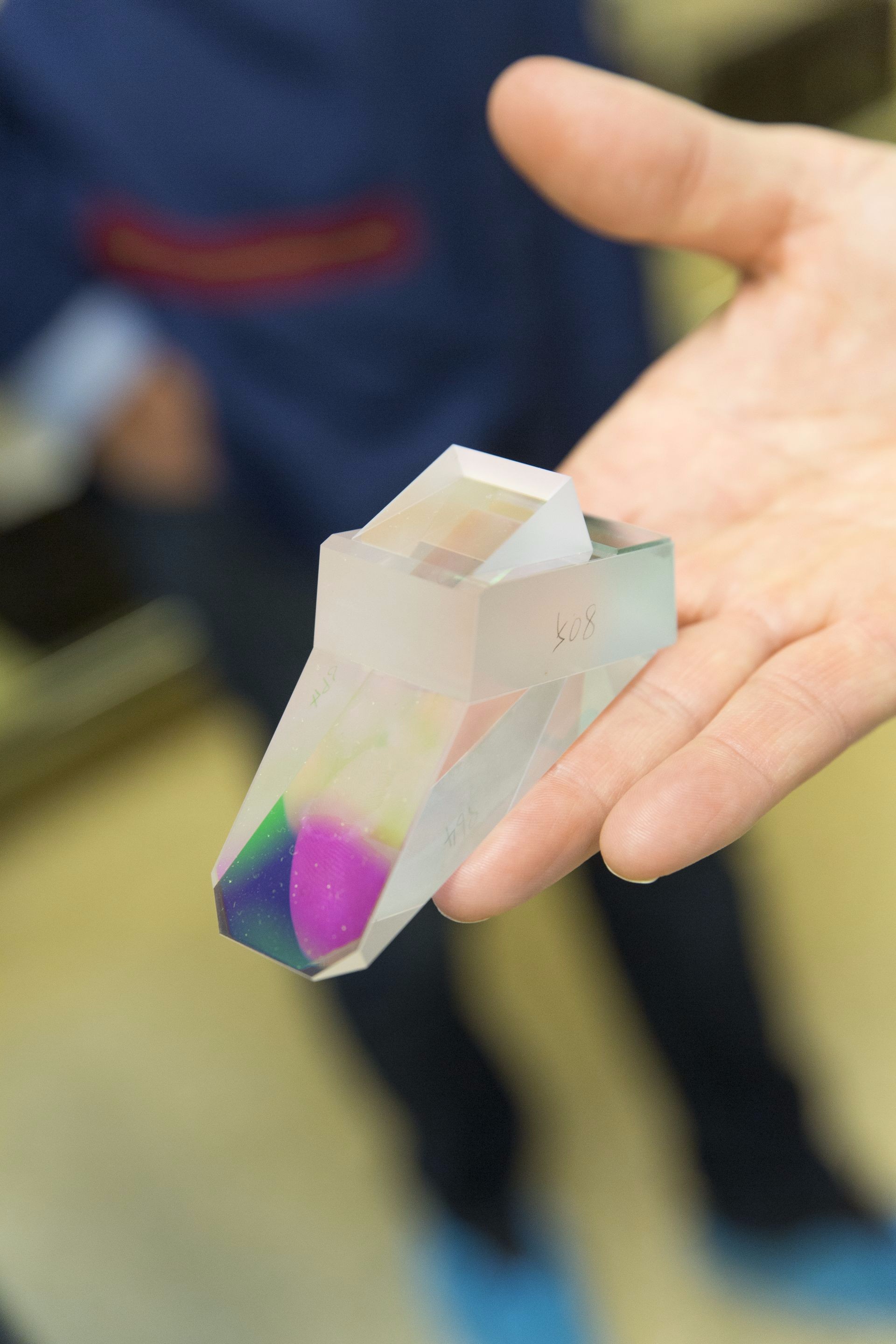
Hertzman remembered a technology developed by AGA back in the 1970s; it was a thermal imaging camera. “The challenge for the thermal imaging camera was how to scan [over a wide area] using a single, very expensive, and liquid nitrogen cooled infrared detector. The solution was to pass the beam through two rotating [octagonal] germanium prisms, one horizontal and one vertical.”
Prism deflections
Hertzman paid a visit to Flir (former part of AGA company) to look at the mechanism, came back, and as Nordenfelt says, “sketched out the idea on an envelope. I ran some [simulations] and this worked out. We could put in a rotating prism and the deflection we needed was feasible.”
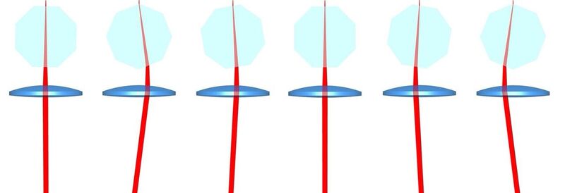
For the SX10, the team developed an octagonal prism that rotates at 1000 RPM. As the beam passes through one facet of the prism it deflects sideways and back again through the opposite facet. As it then passes through a positive lens this is translated to deflection and a sweep of 16 points across (and at an angle from the vertical as the whole mechanism is on a tilt). You get a diagonal pattern (swath) of points as the telescope assembly sweeps up, and diagonal in the other direction as it sweeps down. As the prism rotates, the pattern immediately starts over as the facets progress. Precisely synchronized, this process can be repeated to fill in between previous patterns to densify the point cloud.
The spinning prism that provides the precise and rapid deflection needed to enable scanning in the SX10. Credit: Robert Jung.
With the new spinning prism providing a precise 16-point swath, speeds of 26,600 points per second are achieved. This produces a “full-dome” scan (360° horizontally and 300° vertically, essentially everything above the spread of the tripod legs) in coarse mode in 12 minutes. A full-dome photo pass, if desired is then added in 2.5 minutes. The spacing is always at one milliradian, so by shifting the pattern on subsequent passes the cloud can be densified in increments of 4, 16, or 64 passes. It was envisioned that for full-dome scans a single 12-minute pass would be the norm, with higher densities reserved for selected areas of interest.
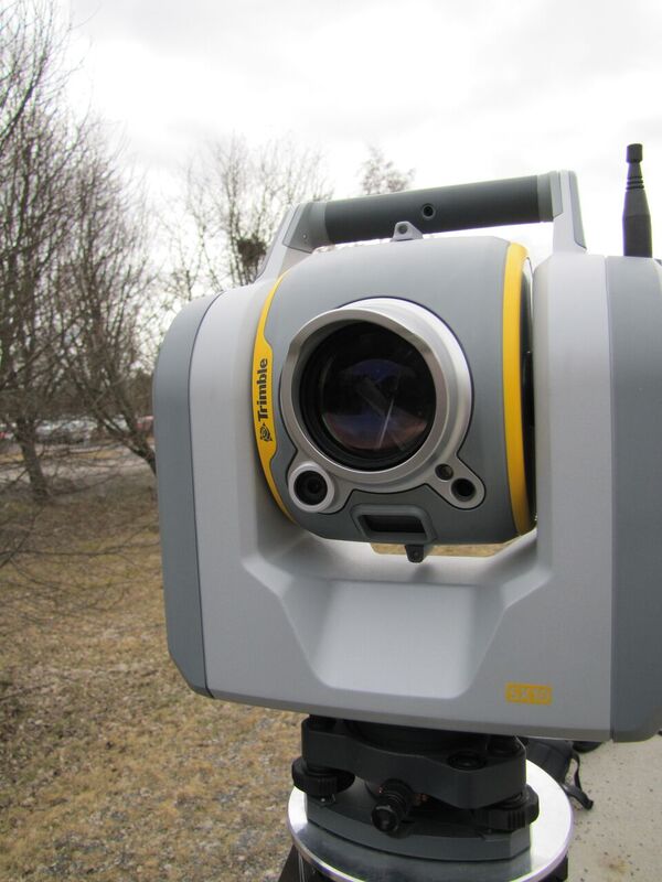
Behind the distinctive “bug eye” of the SX10 is the spinning prism for scanning, a tracking laser, EDM laser, a tele-camera, and tracking camera. Flanking the lens is the overview camera (left) and primary camera (right), and a plummet camera underneath. Credit: Schrock.
The Seed
The new telescope assembly would be multi-tasking at a level never tried before. Advances in technologies developed for the telecommunications industry would be applied, fiber optics in particular. Multiple cameras would be added and would have to work seamlessly and switch automatically. There would be no manual eyepiece (impractical to place down the middle of the multiple beams, prisms, and sensors), and the team would need to develop a tracking system they had not tried on previous models.
There are multiple hearts to the SX10 as is in some of their other total stations. One is a crystal oscillator, synchronizing the laser pulses, rotating prism, sampling returns, and processing.
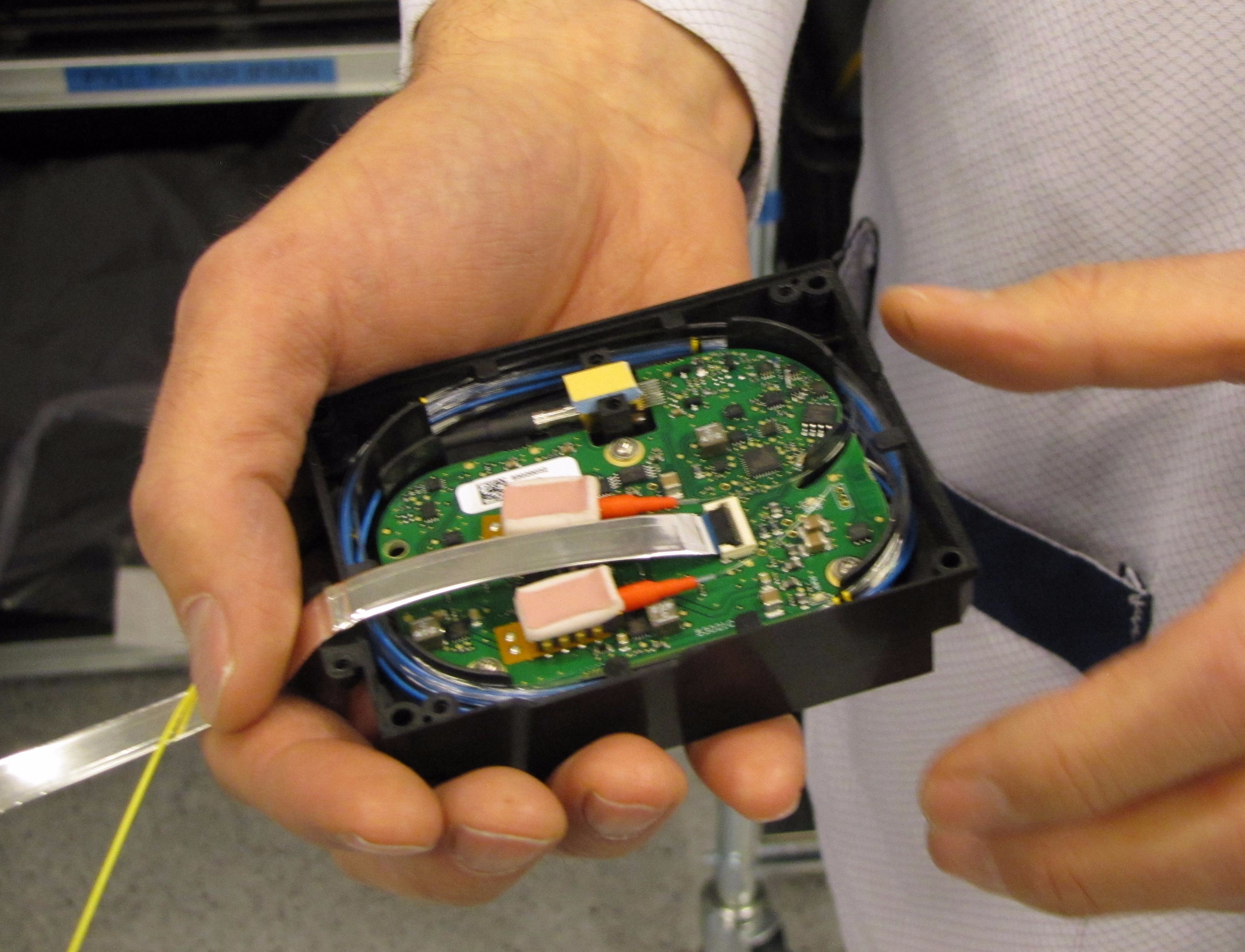
The other is the seed laser. The MOFA, or master oscillator fiber amplifier, is smaller than a deck of cards. It has the “seed laser” and two pump lasers that amplify the signal by, as Nordenfelt says, “pumping in dirty light. The seed laser gives a very nice short pulse with a peak power of 0.1 Watts, then it gets amplified in two stages, with power from these big pump lasers. After one it is 10 Watts, and the second turns it up to 1.3 KW. In between are isolators.”
Beams are isolated from these amplified signals to perform multiple duties: scanning and individual total station shots, and with another laser for tracking. The team has dubbed this multi-tasking EDM as the “3DM.”
The SX10 has 5 cameras and combination of lasers and sensors that the developers have called a “3DM”. The complexity required the development of new assembly, adjustment, and testing stations. Credit: Petter Magnusson – PMAGI AB.
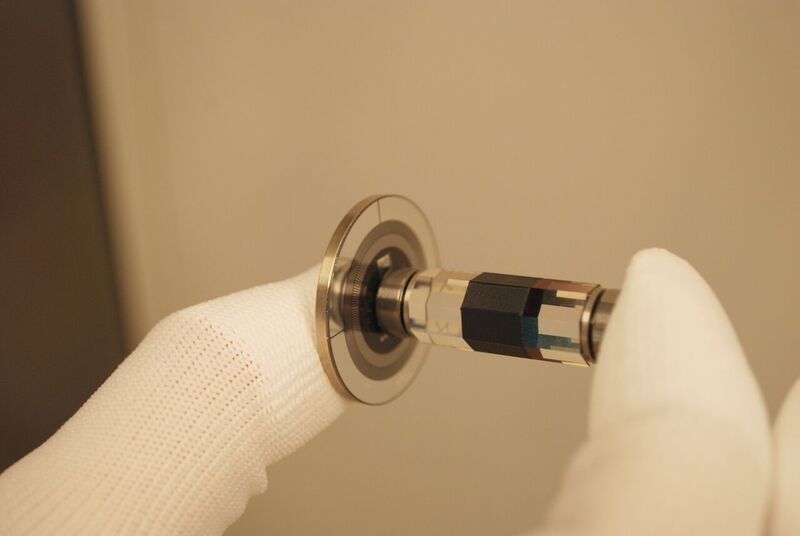
To produce an extremely narrow and tightly controlled beam, the fiber is polished in-house – off the shelf fiber could not meet standards. During the factory tour, manufacturing technician Maik Tegge explained this crucial process. “We put the fiber in the [holder] and essentially break off the end. We have a polishing table that [rotates] to 8 positions so that the same spot is never repeated. [We use five steps] with diamond infused [sandpaper] finer each time. In the first 3 steps the paper is on rubber mats to get the rounded end, and then the final two are on glass.”
Maik showed me microscope views of the finished ends which looked amazing compared to images of standard fiber ends. What they are asking the fiber to do requires this extra care. I touched some of the paper, the first one felt a lot like 600 grit sand paper, and the finest one felt as smooth as glass.
I noticed coils of fiber in the MOFA control unit. Nordenfelt explained that the coils provide necessary delays needed to rest the electronics between the outgoing and incoming signals as the laser is so intense. As this is happening at the speed of light and considering how small the coiled fibers are, I can only imagine that the time increments they are working with are something on the order of what scientists have to deal with when operating a super-collider.
The team says that the result of using such finely produced components together with specially designed optics, “is the smallest spot size in the business. You get a very nice, small spot: 8mm at 50m and only 14mm at 100m.” The benefits of a small spot size would be evident in observing, say, the edge of a building corner; a large spot size will average over a large area down the faces of the converged walls, giving a false location for the corner. Small spot sizes reduce these errors accordingly.
The scale of the sampling of signals in EDMs and scanners, and the SX10 in particular, can be mind-boggling. As explained by Nordenfelt, this only further underscores the complexity of the processing.
“The difficult part of a single pulse is that you need much more power to keep the noise down, and you need a direct sampling receiver. We have an ADC (analog to digital converter) that samples at 2 gsps (two billion samples per second). You need to start recording as soon as you turn it on, and there are only a few milliseconds to record everything [for each individual shot]. If [you picture] a single pulse as one raindrop, and we are sampling at 2 gsps, this would fill 600 barrels, and we are looking for one bucket from all those barrels—every second. Compare this to typical sound sampling at 44 ksps [thousands of samples per second]. This is a huge leap forward compared to anything that a total station would typically be doing.”
How does this translate to precision? Nordenfelt responded: “You need to accurately calculate distance for a small set of samples; the speed of light is 300,000km per second, and at 2 gsps the spacing between samples is 7.5cm. You have to do a lot of processing to look at the shape of the pulse to get down to one hundredth of this length, down to the millimeter.”
Nordenfelt’s good-humored response to my amazed stare after hearing this was, “And that this works is impressive to us as well.”
Excelling as a Total Station
Achieving a small spot size for the EDM was one of many engineering triumphs of the team in getting all of the elements working together to build this multi-tasking “3DM.” The unit not only had to provide scanning capabilities but had to be as good as, if not better in some aspects, than any other total station.
As for the scanning capabilities, the speed would of course not rival the high-end dedicated scanners, but the SX10’s scanner actually yielded a few advantages, like a lower average range noise. In many dedicated scanners, the range noise starts very small but steadily deteriorates over distance. One way to think of range noise is how much variance there might be between groups of shots hitting, say, an otherwise flat surface at a particular distance; if the scanned surface looks rough in the cloud, then this is due to range noise. Other ill effects of range noise in most scanners can be seen in duplicated surfaces and features in the point clouds. The team was able to refine the SX10’s scanning so the noise would remain lower over most of its range.
Nordenfelt said, “The range noise up to 200m is only 1.5mm and 2mm out to 250m; it starts out a bit higher but stays very consistent out to 250m.”
The team emphasizes that their products are developed with direct feedback from many surveyors; Trimble has an extensive network of customers providing input, testing, and involved participation in the market-acceptance phases. This feedback changed the direction of development several times. Once the monumental challenge of adding in scanning capabilities was solved, there were years of refining those capabilities, and with special focus on making the SX10 an even better total station excelling in many aspects.
“The [SX10 was originally envisioned] to be a 2 arc-second instrument,” said Nordenfelt. “And [originally] we thought the EDM might be accurate to 4mm, later 2-2.5mm, and the scanning range at only 250m. But we kept grinding and grinding. Every shot in the scanner was good, and we have a good EDM, so we could build statistics and keep moving things around until we could make things better. Progress was incremental, and we could in the past year go to 600m, increasing the DR (reflectorless) range, and [got to] 1 arc-second.”
Another big step for the team was to take a fresh approach to the active targeting that was the mainstay of their other total stations. While noting that other manufacturers had developed passive camera-based tracking systems and Trimble had used the technology only in some Spectra Precision robotic instruments, the team set out to develop their own camera-based passive tracking, and wanted to add improvements.
One challenge with tracking systems is that the total station might falsely recognize a reflection off things reflecting ambient light (e.g. car mirrors or street lights). Said Nordenfelt, “We developed a new tracker simply because our old one would not work with the new optics. The old one is sensitive to stray light in the optics; a moving transmitter will always create some portion of stray light. So, we left our quadrant [4 diode] detector approach and moved to a camera tracker technology.
“The basic principle is the tracking laser illuminates the prism; it will send light back. You capture an image using chromatic filters only to look for the near infrared light. You then switch the laser off and capture another image; subtract these images from each other; and you cancel out what is the same in both images, which should be anything lit by ambient light. The target stands out very clearly and you can detect it.”
I tested this in the field and deliberately aimed at some potential false light sources; it performed as well as any I’ve tried, but with the added benefit of being able to refine with the tele-camera if needed (more on that later).
Apart from the mag drives (vertical and horizontal axis of the instrument and telescope unit), there are very few moving parts in the instrument. One of the few moving parts is a mirror on a retractable arm for the tracker to swing out of the way during certain scanning, ranging, and imaging functions. I asked about the internal paths of the multiple beams, tracking, and imaging elements, and I struggled to try to diagram this out on a notepad.
One path, for example is the tracker. The tracker transmitter strikes a small prism on the arm and is emitted from the big eye, and the returned signal from the tracked prism is reflected to the back of the assembly—through a giant combination prism, another heart of the system.
Early in development, Christian Grässer traveled to Japan to visit the Nikon-Trimble Joint Venture (NTJV) to see work done on such combination prisms and returned quite excited. The key to these multi-function prisms is in the precise application of reflective coatings and the specialized glues. One cannot afford to have any component coming loose, and the team noted that some of the glues tested were strong enough to crack sections of the glass. There is a lot of glass in the SX10, Grässer says; there are about half a kilogram of glass inside, highly refined glass.
Cameras
All the total stations produced at Danderyd have multiple digital cameras, but the SX10 has five. How does a user learn to use these?
The answer is that you do not have to learn much to master this system: three of the five cameras work seamlessly and appear to operate as one, another is used for the passive tracking system, and then there is a simple plummet camera.
Grässer provided an overview: “This is a fully integrated camera system for documentation, measurement, and instrument operation.”
Starting with the plummet camera, he continued, “The plummet camera is where you start your work; this one is not complicated and is simpler than the previous optical plummet. At 1.5m in height, one pixel opens to 0.3mm down on the ground.”
The plummet camera, as well as all of the other cameras, are engineered and assembled in-house. With the exception of the complementary metal-oxide semiconductor (CMOS) camera sensors, there are no off-the-shelf components (most would not meet specifications).
“The bundled camera system is three cameras: the overview camera, primary camera, and coaxial tele-camera,” said Grässer. “Users experience that as one camera; zoom in and out and they switch on and off very quickly. [Combined] this gives a field of view from 0.65° to 57° and gives an 84x zoom.”
The tele-camera has eight levels; the first six levels get you to 84x zoom. In levels seven and eight, the pixels are quite small and can blow up even further by digital zoom.”
The benefit of this additional digital zoom capability was quite evident during field tests and (among other reasons) convinced me that the loss of the eyepiece on total stations may not be a bad thing.
Grässer gave examples from their own tests (production and engineering teams are encouraged to go out and use the equipment themselves): “At 700m a rail of 50mm was an easy target. The difference between the SX10 and conventional [survey instruments] is the digital crosshair. This is overlaid on the screen, and there are settings for brightness, spot exposure, white balance and so on. You can adjust manually or auto focus.”
At first when I heard the cameras were 5 MP (megapixels) I considered that smart phone cameras often are 2 -3 times that, but I forgot about focal length and very narrow field of view on such small sensors at high levels of zoom. Think of a TV at full HD: there is a lot of detail at the level of each pixel.
Grässer said, “When zoomed, the middle of the crosshair shows the size of laser spot at that distance. 1 pixel is below 1mm under 50m. The digital crosshair points exactly where the EDM points; we tell the cameras to draw the crosshair for the EDM. The position of the digital crosshair depends on what camera is active and is a function of the distance. Thus, distance measurements are always [going on in the] background for the crosshair and providing distance to continuous focus. This includes also sensor data and temperature calibration data.”
The overview and primary cameras are not coaxial like the tele-camera, explained Grässer. “We compensate for that parallax between cameras when we over lay the crosshair. You do not have to trigger distance measurement to do this; it is always on.”
“All glass optics are temperature-compensated and any remaining influences are calibrated during assembly and testing for each instrument. We do a calibration for light fall-off and adjust for color shifts for each camera.” Said Grässer, “We use a reference light to make all cameras perform properly and calibrate for geometry, autofocus, and temperature.”
The tele-camera can be focused, and autofocused, all other cameras are fixed-focus. A lot of work has gone into eliminating distortion between images in panoramas.
Terrestrial photogrammetry is another measurement option. Sometimes there are features overlooked in collecting points by prism or DR shots, or if the area was not scanned or the scanner did not pick up the features then the images provide another option for after-the-fact measurements. Grabbing panoramas at each setup is a becoming a common best-practice for users of total stations that have imaging capabilities. At 50m, one fine panorama pixel is 4.4mm, and the residuals are quite consistent across the field of view. Terrestrial photogrammetry in overlapping images from different stations is done in TBC as the images are already registered.
I asked about standards; Grässer said they adhere to ISO standards, and the standard for length is traced back to the Physikalisch-Technische Bundesanstalt, the German authority for length. The frequency of the reference clock (the crystal oscillators in the instruments) is traced back to atomic clocks.
The Factory Floor
To enter the factory floor, you are given a lab coat and booties (with grounding straps). The entire facility looks shiny and new as there was a recent expansion and remodeling to accommodate the new SX10 line. That expansion required completely different production stations and procedures than those for the S series total stations and scanners produced there.
From visits to other unrelated facilities in the same country I see a lot of what folks have described to me as a particular Swedish-ness reflected in the physical form and working environment at the Danderyd facility. After all, this country of only 10 million has a long legacy of precision manufacturing by investing in research and development for their industries and in the education and health of its workforce.
But there is no stuffiness in the operations. The work day is 7.6 hours; the production workers are highly educated, trained, skilled—and cheerful—and they rotate assembly and test stations daily. The official languages for all work at the facility are Swedish and English. Also, did I mention they can have a beer for lunch (albeit a rather weak “lunch” beer)? The ubiquitous European on-site cafeteria is particularly good at the Danderyd facility, and they did serve Swedish meatballs (köttbullar). To borrow a line from Seinfeld, “They’re real, and they’re spectacular.”
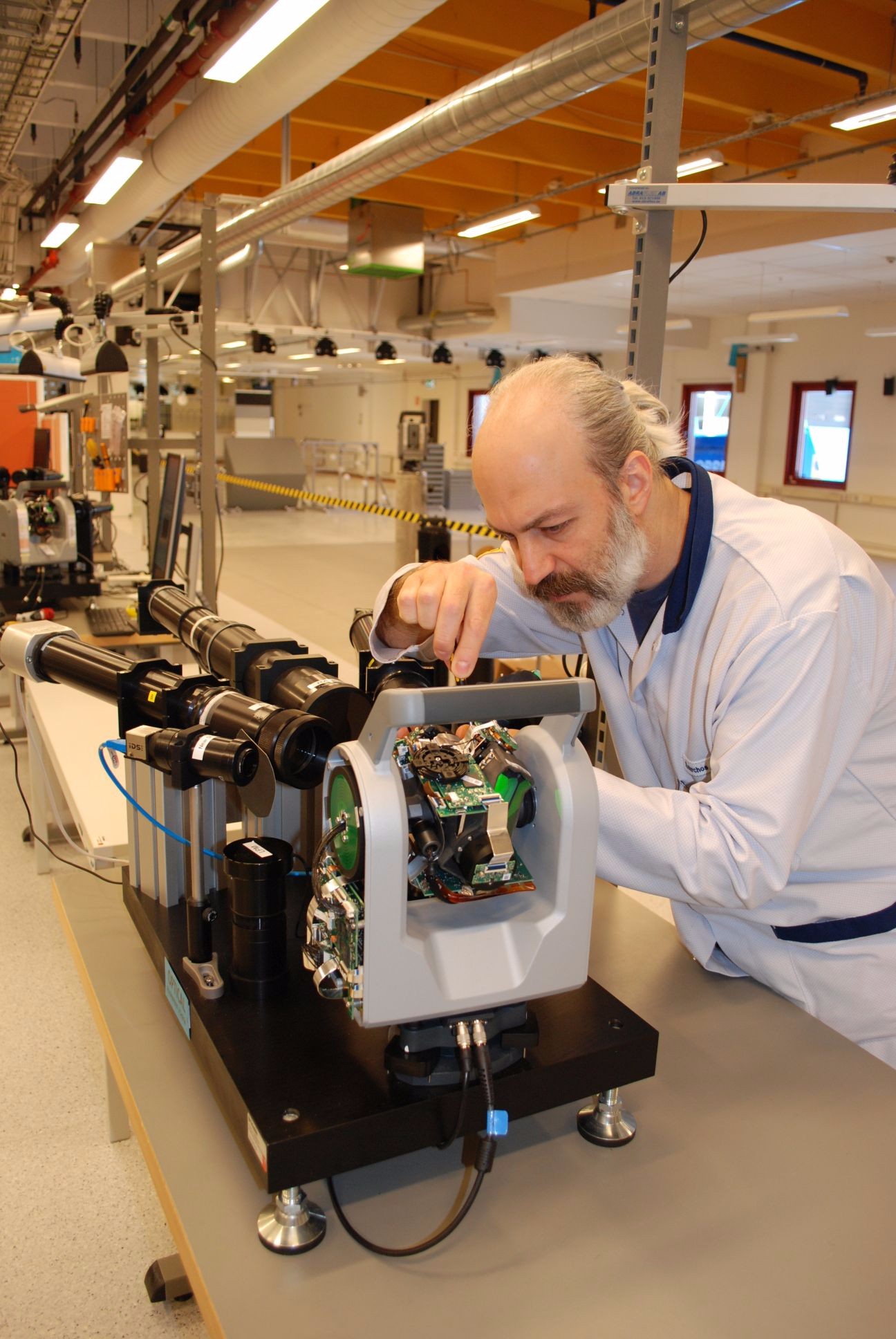
My guides were manufacturing technician Maik Tegge and technical product manager Robert Jung.
“Assembly is done here,” said Tegge. “Parts are from all over, but most sub-assemblies are done here as well. Camera assemblies are done here on the floor and optics are done in a clean room.”
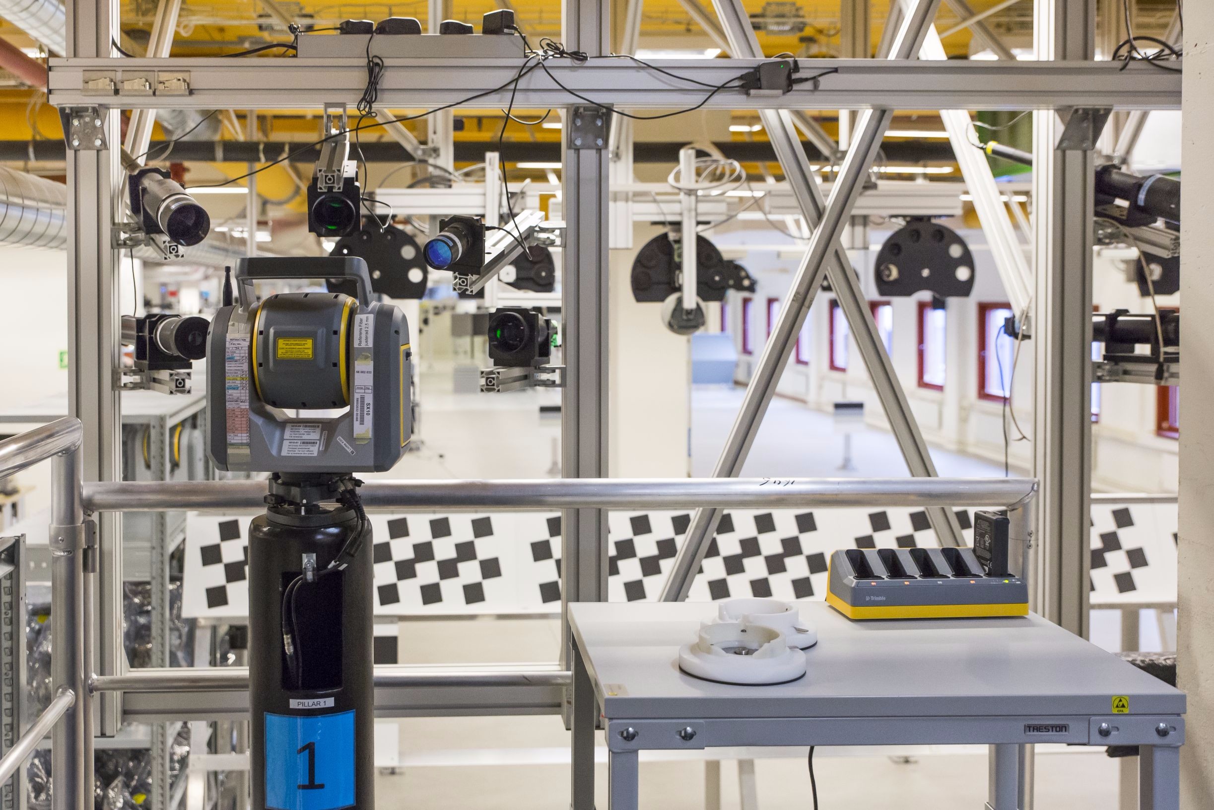
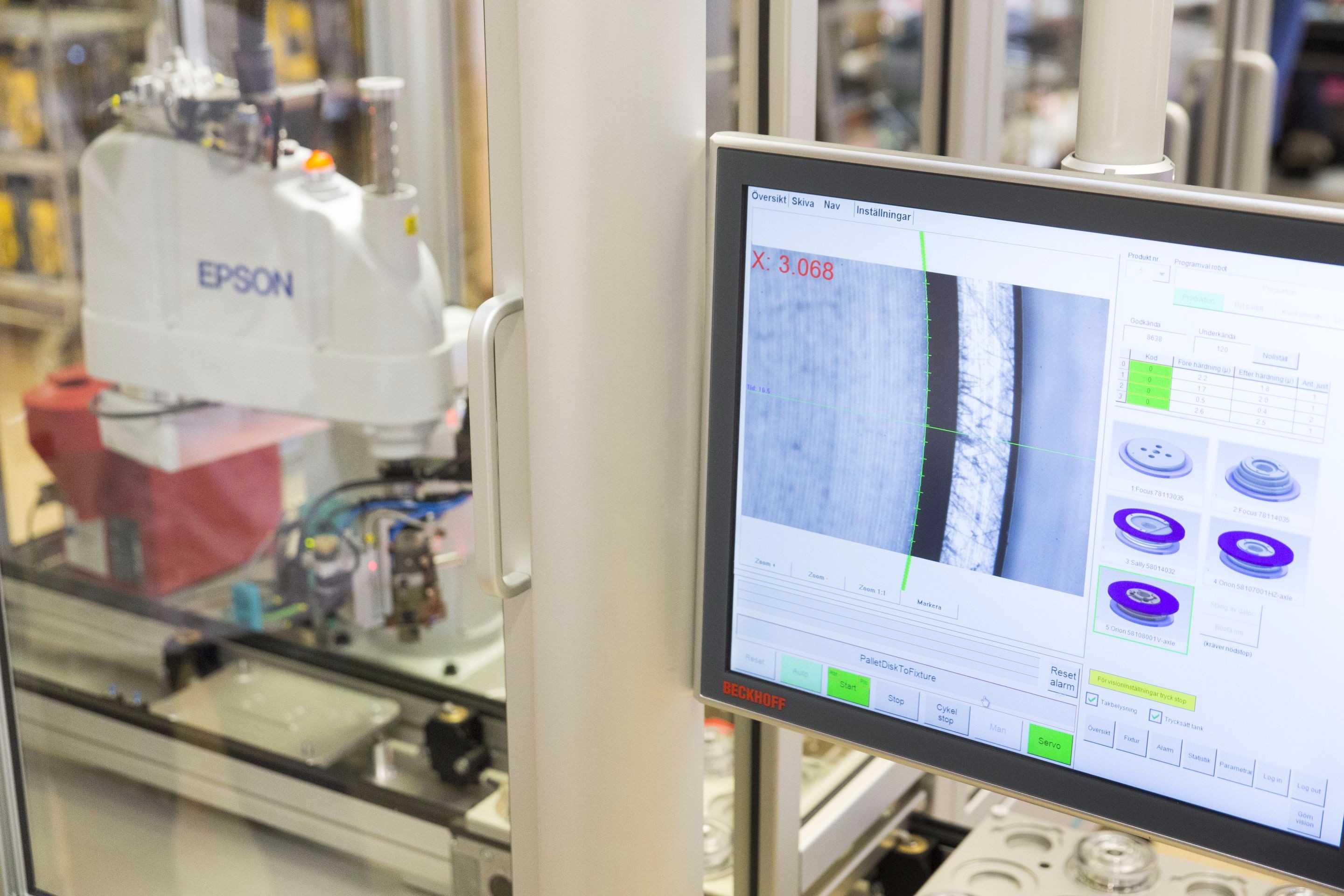
On an elevated platform, I saw one of a long series of test stations for the SX10; sometimes it looked more like a test facility than a factory as there are test stations at every step of assembly. Indeed, every element of each instrument is tested; all results are put into a database indexed by each individual instrument that can be accessed during not only its assembly but throughout its working life.
On one raised platform overlooking the factory floor were several mounts to test the EDM and cameras, hitting targets very near and as far as 167m away. From each station, you have targets ranging from collimation targets, checkerboard and color patterns, to mirrors bouncing from the back of the factory floor. A long test interferometer spans the full length of the floor; 167m but there are 3-fold mirrors to add length. Test interferometers are themselves tested and calibrated frequently by an independent external team with their own equipment. Two climate chambers on the platform enable the same test at the high and low end of the designed range of -20°C to °+50C.
Tegge said, “The tests are cycled, [for example] the primary camera going to the targets, looking at sharpness on checkerboards; and we do distortion calibration [at this station] as well.”
In another room is a window where very long-range EDM and camera tests are done (with the window open and closed) to targets on distant buildings; one is 2.43 Km away.
I noted that we were on the second floor of the factory; was there any concern about the stability of the floor? As it turns out (no surprise) even that is monitored. Several S series total stations are constantly checking for deflections, and this is processed in their own monitoring software, Trimble 4D Control (T4D), which is widely used for the monitoring of buildings, bridges, and dams. There are also large stone tables for calibration and testing of compensators.
Tegge said, “There is total trace-ability of all components, when they are built and inspected, and the various calibration processes are all kept in the database. All production staff are trained on all stations and rotated. This is in stark contrast to some factories.”
One of the notable robots in the facility, in a climate-controlled glass enclosure, assembles the glass disks for vertical and horizontal motions of the mag drives. One of the few components shared by the S series and the SX10, these disks use pairs of light emitting and receiving diodes hitting the etched patterns to precisely measure angles. Such assembly is best performed by a robot, though the floor staff mentioned that they knew of other factories where manual assembly was still done with jigs.
The Hair Cross
The SX10 does not have a physical crosshair (or “hair cross” as they call it in Danderyd). Crosshairs were traditionally the single reference for all collimation calibration and testing. On the surface, having no crosshair looks like a real challenge for collimation, but keep in mind that physical crosshairs can only be adjusted to a few microns while a laser spot at very short range can be a single micron. The team had to rethink legacy processes; Tegge explained that the beam axis of the main EDM laser is calibrated, and then all other collimation uses that as the reference—the tele-camera, tracker, spinning prism, and all internal: lenses, mirrors and prisms.
On an assembly line for conventional total stations, many of the test stations will have a single (or pair) of telescopes/sensors aimed at or through the main axis of the instruments’ telescope assembly. The SX10 test and calibration stations mostly have three or four such telescopes peering into the inner workings of that distinctive large lens.
I asked again about the tilt on the main mechanisms within the SX10 telescope assembly. While this was done mainly to put a tilt on the scanned pattern, it was also noted that the tilt would leave options open for further development (but I did not press any deeper). One station is a small black-walled enclosure (just big enough to fit an instrument inside) where all of the cameras are color-calibrated. A consistent grey color is used as a baseline for all adjustments.
There are test and assembly stations for other products produced at the facility; only a few stations are the same for both the S series and SX10, like for compensators and tilt sensors. Tilt sensors are liquid surface, camera-based, with two axis mirrors and silicon oil. The optics are individually calibrated and tested, and each laser is pre-adjusted for strength and position; this is microscope work as even the tiniest speck of dust would cause a rippled effect in the resultant spot like a stone in water. Some work is reserved for the clean room.
Apart from some off the shelf test equipment components, tools like torque screwdrivers and robots that assemble components like the angle measurement discs, nearly every jig and test station is designed and manufactured in-house. The factory has a very well-appointed machine shop.
Manufacturing technician Maik Tegge and technical product manager Robert Jung explain the design of the “S” series total stations to the author. Credit: Petter Magnusson, PMAGI AB.
In addition to the assembly and testing stations for the SX10, I was also shown those for the “S” series total stations and TX scanners. The TX8 and TX6 scanners are assembled in Danderyd (with much of the engineering done in a facility in France). In 2003, Trimble acquired MENSI, the French company specializing in scanning hardware and software; they also produce the Real Works scanning processing software and the related module for scanning in TBC.
Tegge showed me an interesting solution installed in the factory for testing the scanner beams; a series of long corrugated pipes (that I mistook for ventilation pipes) cross back and forth along the ceiling of the bottom floor of the factory. The beams enter one pipe, and that is connected by mirrors to many more pipes to test the beams over different distances in a complete laser-safe environment. One test station for the scanners is under an awning outside one of the windows for tests in exterior conditions.
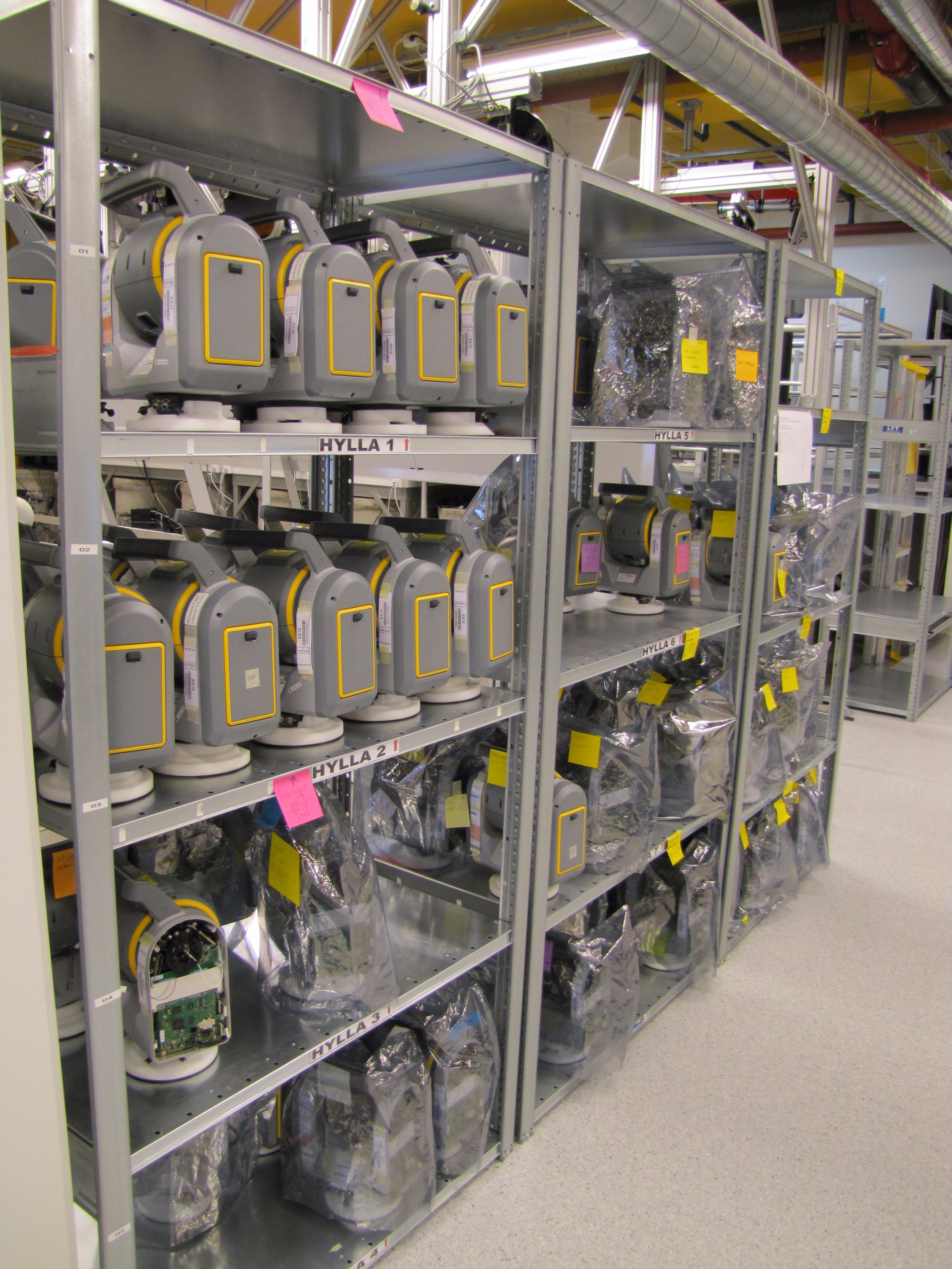
Radios are added to the SX10, and a final round of tests before they are shipped out. While standing in a room with shelves full of various completed instruments awaiting final testing and shipment, I asked how the market for these new units has been. Jung replied that demand for the SX10 has been very good, and the demand for the S series total stations and scanners has remained strong.
Test Drive
The scenario I wanted to test with the SX10 was one of a pre-construction topo that would include developed and undeveloped land, an existing building and road, and a survey/property report. In the U.S., a common type of property report survey is an ALTA (American Land Title Association) survey. Such a survey is often requested by land tile companies and lending institutions to include boundary, topography, existing structures, utilities, easements, etc. I have encountered many surveyors who have added scanning and/or imaging to their property report surveys, and when I heard about the SX10 I thought that this might be well suited for this particular type of survey and many more.
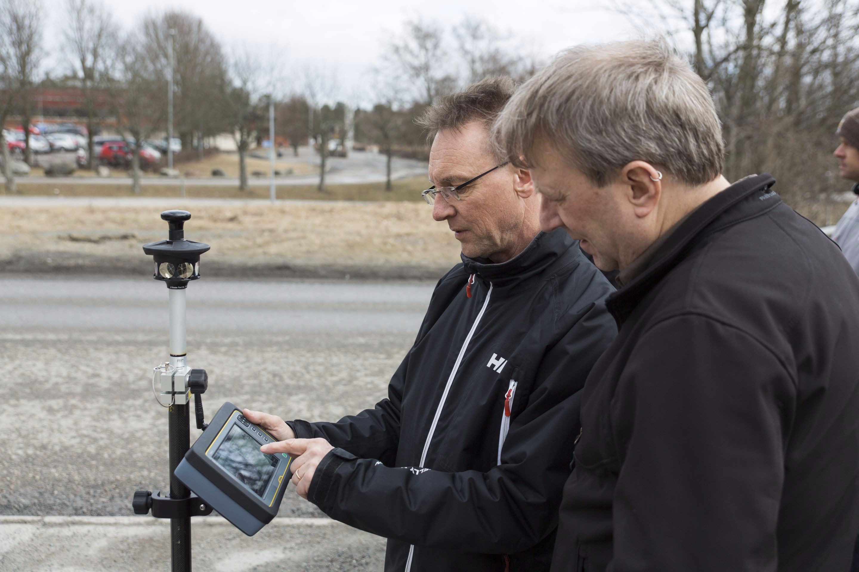
Jung was my guide through the operation of the SX10, and we set up for the test survey adjacent to the factory; Jung had previously established some survey control marks and there were several targets on the factory and surrounding area we could check in to.
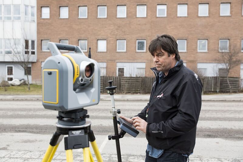
Joining us on the test survey was Lennart Gimring, Survey and Mapping Manager for ÅF Infrastructure AB who was an early adopter of the SX10. Gimring reports that the rollout with his crews has been quite smooth. Credit: Petter Magnusson – PMAGI AB.
We were joined by Lennart Gimring, survey and mapping manager for ÅF Infrastructure AB, who was an early adopter of the SX10 and participated in the customer-acceptance testing of the instrument.
“ÅF does all kinds of work including topo for construction, project design, roads, indoors and, runways,” said Gimring. “We like scanning because we can combine it with many other data sources such as lidar from helicopters. With the SX10, we can see areas we might miss with other types of point collection, scanning and images.”
His company is a large international concern providing technical services, tech consulting, infrastructure engineering, supporting industry, energy, hydro power, nuclear power, and more.
“We have about 9,000 employees in Sweden and a total of 11,000 worldwide, and a network of partners with about 29,000 people” said Gimring. “We do not try to do everything ourselves; we depend a lot on our partners.”
Gimring recognized some advantages in using the SX10: “What struck me as the best benefit is that before you leave a site, you can do sweeps of scans and images and get things we do not normally get, avoiding that second visit.”
In addition to avoiding missing data, Gimring saw that having these capabilities for every crew could enhance the utility of the data. “We can have data we can present to the different tech disciplines. If it is a bridge and the clients want to see the as-built of what it looks like, you can give them the model. With the model, they might not need to go out to the site to start [exploring engineering options]. They can improve their engineering workflow.”
What advantages does Gimring see from the imaging capabilities? “We try to use the images as much as possible; it’s definitely important. People can actually visualize what is there. Some people still want CAD drawings from the data, but if you approach them and show them you have this as well, then they definitely see that as an advantage.”
I asked how the roll-out with his crews is going. “It is just as capable as previous generations of total stations. It is a little bit bigger but you do not have to drag a scanner along. Sometimes we would [bring a dedicated scanner as] we do a lot of work with industry [plants and factories], but we have no problem combining with that data. Maybe it is not the ultimate Swiss Army knife, but for most work it means you can do more without having to take so much [gear] along.
“My people who use this say it is very simple. If they used an [S series total station before] it is the same thing, and the scan is another added feature. For us it seems cheap as we do not have to buy another instrument. We try to stay ahead of the cutting edge, so we mostly lease our equipment. But the SX10 was so much of a change that we bought this one.”
Is the slightly larger size an issue for his crews? Gimring said, “One crew that always wants to use this as the first option is made up of two women who have no problem carrying it around. They quite like it.”
Gimring mentioned that the next day he would begin an airport runway project: “It is important to keep the runway open; we need to scan as we cannot enter the site. So we will do this from a roof hundreds of meters away.”
For our test, we did a first setup, central to the site, and did a simple resection. Gimring and Jung noted that in Sweden a standard practice is to use a GNSS rover to establish the control connecting to the Swedish national VRS network (SWEPOS). Indeed, the SWEPOS network is one the densest and best operated in the world (I visited their operation the day before and an article is in the works).
The operation of the SX10 is so familiar and simple—essentially that of a typical total station, with some enhancements, and working through a tablet. People who have been working with robotic total stations are used to controlling everything from the rod, but with most systems you do not see what the total station sees. And you may only look through the eyepiece of a conventional total station during setup.
This is not much different. I was actually hooked on robotics using Geodimeters two decades ago, so I find using the tablet provides a lot of utility. With the split screen, I can see what the SX10 can see on one side and control the data input on the other side of the screen.
Though we did not set up over a point for this exercise, I tried the plummet camera and noted that I could capture the image, station data, and compensator data on the same screen. Imaging is great, but capturing an image with (potentially) every shot is going to settle a lot of arguments back in the office.
We started picking up features individually, as we would with any total station, both with the rod and DR. The tele-camera and digital zoom levels made for some interesting shots. For example, an electrical tower over 200m away: this was a good test for the zoom and crosshair control. Sags on the overhead lines were also well defined in scans and were easy to collect in DR mode. We easily picked up an insulator on the distant tower we would otherwise barely be able to see without the digital zoom. You can point manually or do this on the tablet, holding keys down for rapid movement and then nudging when you get close.
There was one thing we could do that we cannot do with a many legacy conventional total stations: move the instrument in very small increments. Using the tele-camera, we were able to nudge the cross hair by one pixel at a time via keys on the tablet. It’s especially impressive at higher zoom levels.
Prior to the visit, I had asked a lot of surveyors what their misgivings might be about the instrument, and the loss of the eyepiece was most often mentioned. But when I asked if they had worked through a controller or tablet using the total station’s camera yet, they mostly said they had not, so it would be difficult to make a direct comparison.. I know that the image though an eyepiece looks a lot crisper than through a transmitted cameras image. But when you have higher magnification plus digital zoom available, I am pretty sure many folks (once they’ve tried it) might conclude as I (and some early adopters I’ve spoken to) have that working in this manner actually is a dramatic improvement.
It’s an acquired taste though. Among surveyors, there are still two camps when it comes to on-board control vs. external controllers. I guess I am more in the camp of preferring the mobile controller and not being stuck behind the instrument poking away at it. Out on the rod, robotically you get to control the shots, and you are getting good data. The tablet and camera, in my opinion, takes that up to a new level. I can really see what the instrument is seeing, and see it better (in the case of digital zoom) than I could with my own eye behind an eyepiece. Taking this even one step further, I could see performing a lot of the survey (at least the scanning, imaging, and DR shots) remotely via the tablet from the comfort of the truck: something on my mind in the biting March winds of Sweden that day.

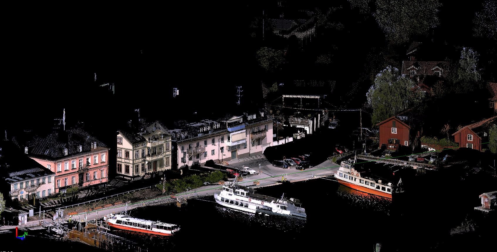
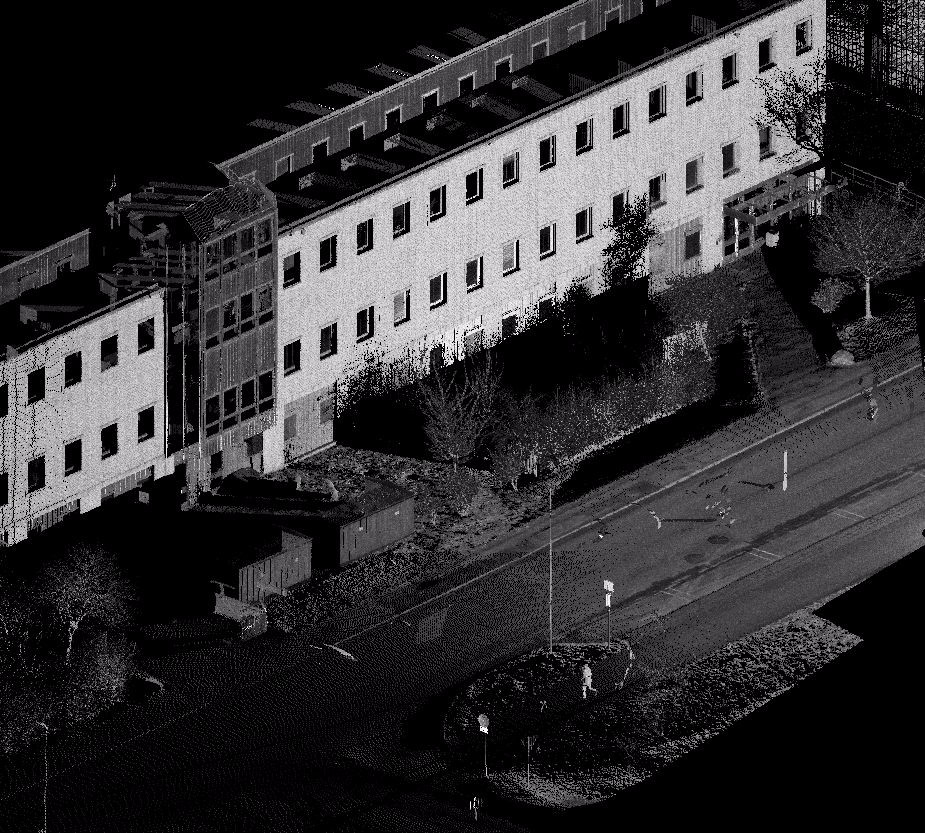
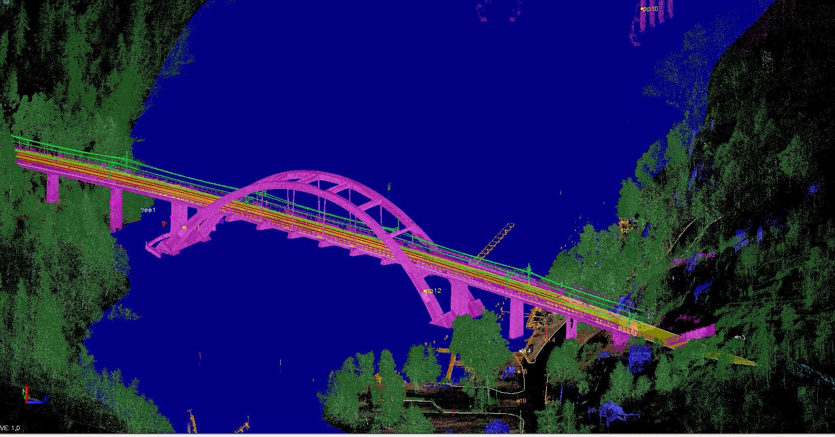
Scan cloud from our test survey as displayed in TBC. The face of the Danderyd facility captured in coarse mode, with two areas of interest (left and lower right) scanned at 4x mode. – Credit: Schrock.
During the test survey I looked for objects that might have otherwise caused a false lock when using legacy active tracking, like a distant road sign that had glint of the low March sun on it. The tracker had no problem distinguishing the prism from the glare hazards, as well as some tests next to windows reflecting the sun. We decided to do selected scans of small areas of the building in coarse mode, then at the 4x scan level.
The areas of interest were easy to pick on the screen, and while the scanner went about its business we got to do some integrated surveying, in the same project and on the same tablet. This popular option allows you to take a GNSS rover (while the scanner is busy) and pick up features that the scanning and imaging might not be able to see without extra setups, such as flowlines of gutters, sticking the point of the rod into the mud and leaves to contact the surface and capturing some objects behind cars and hedges.
When the survey was complete, we did as Gimring suggested and did a full 360 scan (cutting off only the empty sky above the building and directly overhead). This took about 10 minutes in coarse mode, and then we added a full-dome of images after, which took about three minutes more. One advantage of using a total station as a scanner is that the scans are pre-registered, and you do not have to provide as much overlap as you would with conventional scanners for the processing software to combine the scan into a single cloud. No more target balls as well, of course. You can add free stations too, setting up the SX10 without tying into the control network if you provide some overlap.
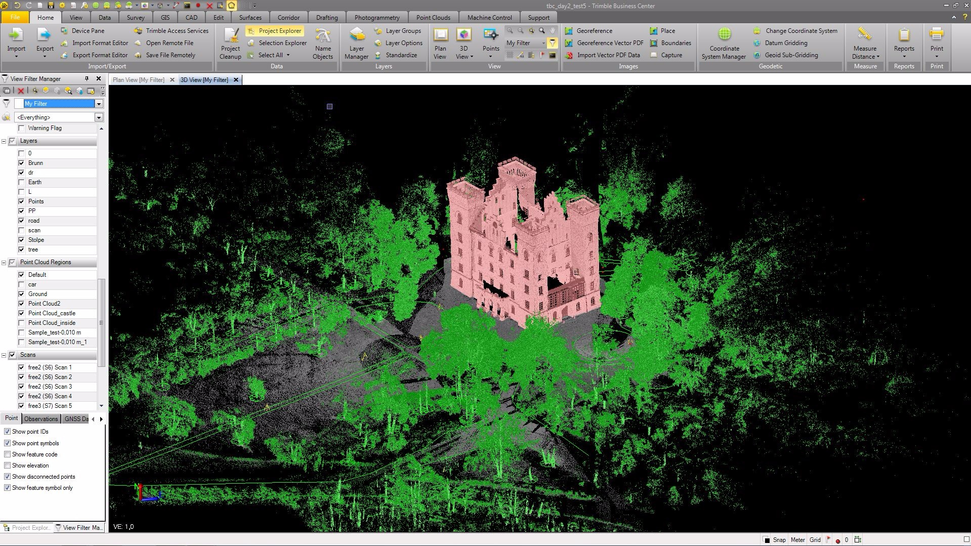
Looking at the data in TBC afterwards had me thinking: all this rich data collected on one instrument, far more data than I could have gathered with a conventional total station in the same amount of time. Registered images and selected scanned features, all tied into the adjusted control, integrated GNSS shots as well. Even the coarse-mode scan defined features quite well.
More Gets Easier
This is the way a number of manufacturers have been heading: enabling surveyors to provide clients with much better data to enhance their workflows. Enriched data is addicting, and once clients get a taste they will (and many already have) demand more. One surveyor told me that he would never need one of these instruments for construction staking; certainly, there are simpler and less costly mechanical instruments that are well suited for that. But I got to thinking that even for a small shop that does a wide variety of work, having such capabilities is not limiting in any way, but instead enable a broadening of one’s marketable services.
Total stations continue to evolve into something that might have seemed like science fiction to us several decades ago, but they will continue to be one of the essential mainstays of precision surveying. I tend to chuckle at statements or ads implying that “this or that” solution means that surveyors do not need a total station anymore (not surprisingly, such statements seem to come from those who do not make total stations). Not even close: total stations are often the final answer, that with which the precision of other solutions can truly be tested: the highest precision arbiter. Scanners, drones, GNSS, and terrestrial photogrammetry are not going to eliminate total stations. On the contrary, it appears that the ubiquitous total station—hailing from its humble origins in quadrants, transits, and theodolites—is the optimal instrument on which to grow capabilities or integration of multiple measurement technologies and solutions.
The SX10 represents a big stride ahead, and the global team involved should be rightfully proud of their accomplishment in developing a whole new platform: new, but one that can be operated with the ease of familiar instruments. I asked Stella Einarsson what the future might hold for the SX10 and instruments to follow.
“I think that someday these [features] will simply be what is expected for total stations.”
I tend to agree. I hear some folks ask “why” add such features, and I have not found any compelling reason not to.
In short, of course, I enjoyed learning about and trying this new solution. I was as giddy as I was when I tried my first EDM in the 1980s and first robotic Geodimeter in the 90s. I’m so glad there are folks like Einarsson and her team looking ahead for us.
Additional photos and graphics: