The new version of Esri’s ArcGIS Pro software offers the capability to use stereo imagery, something of great use to those looking to digitize and use 3D vector data. To this end, I thought I would try bringing in some stereo aerial data to see how the process works within ArcGIS Pro.
Vague Knowledge
At this point, I’d like to point out that there is an Esri help page on this subject, but even though I have used stereo imagery before from survey suppliers, I still found the instructions a little vague. So, the instruction laid out here will be in a readable and repeatable format.
What You Need
Before we start, it is only fair to point out that you can’t just download some stereo imagery and bodge it through a process. Far from it: you need the survey specification and calibration report. Failing that, you need the camera specifications (rows and columns) and the information of the set up during capture; this will include information such as image format, pixel size, principal point, and focal length as a bare minimum as well as the table that has the specific image information (perspective x,y,z, omega, phi, etc.).
Let’s Get To It!
First, we need to create an ortho workspace. By doing this the process creates a mosaic of the images, then loads them into a correctly referenced data frame.
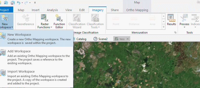
At the top of the screen, select the imagery tab, then select new workspace.
 This will provide you with a new interface:

Provide the workspace with a name and description (this is more for reference). Then, choose the “Aerial – Digital” in this case.
A new interface will present itself:

Here you will require the camera and survey specification. Notably, there should be a table that has the image information such as the perspective, kappa, phi, and omega.
Frame Table
Here is an example Frame Table:

OBJECTID: Required field – Needs to be unique and relatable.
CAMERAID: Required field – Links to the Camera Table. If using multiple cameras, these must be linked correctly. Please ensure the ID is in the same format as that above, as it has been found that errors occur when different formats are used.
RASTER: The relative location of the image(s) in relation to the Frame Table.
PERSPECTIVEX: Required field – The x-coordinate of the perspective center, in the ground coordinate system. The units are in the coordinate system units.
PERSPECTIVEY: Required field – The y-coordinate of the perspective center, in the ground coordinate system. The units are in the coordinate system units.
PERSPECTIVEZ: Required field – The z-coordinate of the perspective center, in the ground coordinate system. The units are in the coordinate system units.
OMEGA: The rotational angle of the camera’s x-axis in degrees (decimal degrees).
PHI: The rotational angle of the camera’s y-axis in degrees (decimal degrees).
KAPPA: The rotational angle of the camera’s z-axis in degrees (decimal degrees).
Cameras Table
Once complete, you will then require a cameras table; see the example below.

CAMERAID: Required – ID of the camera that relates to the frame table for the images. Must be in the format shown above.
FOCALLENGTH: Required – The focal length of the camera lens, measured in microns.
PRINCIPALX: Required – The x-coordinate of the principal point of the autocollimation, measured in microns.
PRINCIPALY: Required – The y-coordinate of the principal point of the autocollimation, measured in microns.
A0: Required – Coefficient of the affine transformation that establishes a relationship between image-space and film-space.
Can be calculated by =+((NUMBER OF COLUMNS/2)-0.5)*PIXEL SIZE IN MICRONS
A1: Required – Pixel size in microns (must be positive).
A2: Required – represents the skewing of the x direction. For this to work in practice, I have found zero is required.
B0: Required – Coefficient of the affine transformation that establishes a relationship between image-space and film-space.
Can be calculated by =+((NUMBER OF ROWS/2)-0.5)*PIXEL SIZE IN MICRONS
B1: Required – represents the change of scale in y direction. For this to work in practice, I have found zero is required but Esri provide this as:
B1 = my * cos t
Where my is the change of scale in y direction, and t is the rotation angle, measured counterclockwise from the x-axis.
B2: Required – represents the change of scale in x direction. For this to work in practice, I have found zero is required but Esri provide this as:
B2 = my * (k * sin t + cos t)
Where k is the shear factor along the x-axis is equal to tangent of the skew angle. The skew angle is measured from the y-axis.
SRS: Not required – I use this to ensure the software automatically reads the coordinate system and doesn’t require more input. This is the EPSG code for the data.
Away You Go
If you entered everything correctly, you just hit “next” and away you go. If not, you may be in for a world of pain, as in practice I found that the ID fields HAD to be in string format and all the numerical fields in numerical format. Furthermore, comma-separated tables (CSV) were preferred over the standard XLS.
