Alignment-based utilities are the key to BIM for civil engineering.
It might sound odd to think that pipelines and conduit runs can play a key role in the evolution of BIM for civil engineering. In fact, you might wonder what I mean by “BIM for civil engineering.”BIM is a set of objects in a software that properly contains your design, shows in 3D, and generally matches how your industry does things. Programs like Autodesk Revit and Graphisoft Archicad do this for buildings. The term BIM became popular from them and implies you are not drawing lines and arcs anymore; you are creating industry-appropriate objects. Whatever your opinion of the meaning of BIM, that is the definition I am using here.
Any useful BIM object must be carefully programmed to contain the intended parametric design data, which allows for proper editing and data extraction. For a pipeline, that foundational parametric data has long been established and is in every civil engineering design package out there. It generally is called a horizontal and vertical alignment.
Once you see that a proper pipeline BIM object is just a horizontal and vertical alignment with additional data and you make a system that stores the data outside of drawings for easy sharing, you can apply that pattern and make many other civil BIM objects, such as conduit banks, walls, and drainage channels.
Why Are We Using Hub and Spoke Models?
The current trend is that software makers are modeling with “hubs and spokes,” sometimes referred to as “part-based modeling.” In that schema, each spoke or part is a horizontal line or arc, with an elevation at each end. Then you have structures, or nodes, between the parts. This is what hydrology and water modeling tools require, so such a network definition is not new.
It is useful to be able to see calculation models in 3D, but final design is done differently and has different data. People commonly misunderstand this, as they say, “You can make a hub-and-spoke model mimic the physical shape of your designs.” Yes, after design is done, you can.
It’s painful enough to prevent most people from doing it consistently though, assuming you have the budget available. Attempts at automating the creation of hub-and-spoke models from alignments are only partially successful, as the hub-and-spoke models still want to assert their own design rules, and that becomes an effort to manage, also.
Unexpected Kinks
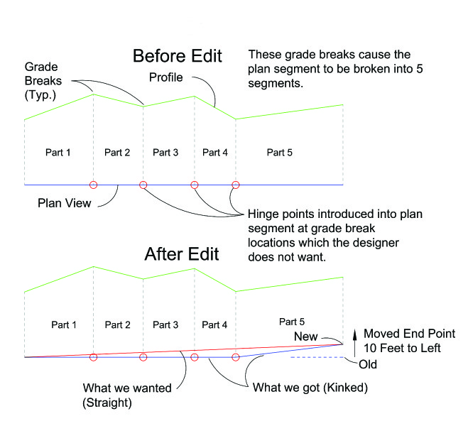
Here are a couple of examples of bad things that happen when you try to turn true alignment data into hub-and-spoke data. Imagine if you had a 1-mile long pipeline and the profile changed grade five times to follow the terrain. The part-based data would have five parts to it, numbered one through five.
You discover that the right-of-way line you are supposed to follow rotated just a bit such that one end stayed and the other end moved 10 feet to the left at part five. So you zoom into the end of part five and move it 10 feet to the left. The result would be: parts one through four are unaffected, but part five now connects from part four to the new point. You just kinked the pipeline, but it would be such a small kink that no one may notice.
1 Mile Pipeline
Here is the bad part: when they do notice, there is no way to tell if you kinked the pipeline on purpose or by accident, as there is no record that your original horizontal alignment was one segment a mile long.
The same thing happens for profiles. Imagine if you had a trunk sewer at minimum slope its entire length. That is one segment in profile. The horizontal, however, is three lines that go from manhole to manhole around a large radius curve. This is the reverse of the previous example. The part-based approach would split the profile into three segments.
You are told that the downstream connection point is 6 inches lower than previously thought. The designer changes the downstream elevation, and the result is a kinked profile.
Again, anyone reviewing the design would have little reason to question it, as it is common to run sewers at minimum slope to minimize their trench depth, then steepen them on the last segment to make the connection point. They would never know that the intent of the sanitation district was to maximize slope along the whole length and avoid grade breaks that cause undesirable flow turbulence.
I provide examples where the changes are minor, as that’s when they are hardest to notice, but the fact is that even when a designer is watching closely, he or she has to take the time to edit more things than they should. Editing the sewer profile mentioned here should just be modifying the connection elevation, and it would straight grade to the other end. You would not have to edit the elevations at the two manholes between the ends. If you did want a grade break somewhere, you would add it and break the profile into two segments.
When you handed that model off to someone, say the owner at the end of the project, he or she would have the real design. When you need to know elevations at intermediate manholes, the software would calculate it from the profile. You can see that this approach minimizes the “hinge points” in both plan and profile. That must not be compromised on, as undesired hinge points are how design mistakes happen, yet they look perfectly good to most reviewers.
Response from Software Developers
I have explained this problem to many people working for the larger software makers, such as Autodesk and Bentley. What I have observed is that they understand it, but they do not want to mobilize their teams to make the needed changes. I agree that the changes would be deep in some cases, and it’s risky to face your teams to say architectural-level programming changes are needed. What they fail to understand is that much of the value of other portions of their software is lost if you cannot easily make utility models. In particular, it is still difficult to convince precise graders that they should produce a surface for their finished ground. What do they need it for if they have already annotated their pipes with elevations? If they knew that they were producing a set of pipe objects that needed it from the start and that it was not some huge extra effort, they would take the time to make the surface.
I have seen designers with Civil3D use alignments for their roads and main pipes, knowing that those tools are related to roads and pipes. They simply recognize that there is no proper BIM data object for what they do, so they stick to things that are as close as possible to their needs. Then the road designers may not make complete surfaces either, because they know that the pipe designers will not utilize them fully.
The whole system is stalled by this, and even the software makers don’t see the point in fixing things, as they see the fixes as enhancement. Why would you enhance something that’s not being fully used now?
Creating Proper Alignment-based Utility Objects
I have seen proper alignment-based utility objects solve the problems firsthand. I currently work at an engineering firm, Hunsaker & Associates, Irvine, and have been there for 15 years. Throughout my career, I have been programming in AutoLisp, VB6, .net, and other languages to fill gaps in tools and workflows as needed.
This led to the development of a proprietary tool in AutoCAD I call the “3D Alignment,” which is just polyline that knows its horizontal, vertical, and “side” alignment data apart from the actual polyline entity data. A side alignment is optional horizontal geometry of something with a profile based on street stationing but that doesn’t lie on the street centerline. You can also add additional data to tell the 3D alignment it’s a pipe or something with a section like a v-ditch or curb and gutter.
It can display itself in 2D or 3D. If it’s a pipe, you get a 3D polyline for the invert and 3D solid for pipe walls. If it has a section, you get 3D polylines at section grade break offsets. We use those to make surfaces, so really this tool is for modeling anything. It also draws text at profile grade breaks, so you can see the data the solid was based on, which is difficult to do otherwise in 3D coordination meetings.
This tool has allowed our teams to take the alignment data that our regular plan and profile workflows produce and display it in 3D without having to maintain separate objects. It also allows us to quickly input profile data not already contained in alignments, as it has a plan-view editing interface for the profile.
Others could easily write similar alignment-based 3D tools, and hopefully will. It is handy to have a working example though, and we have used it on real jobs with real client relationships at stake.
Our tool does not yet qualify as BIM by my definition (creating industry-appropriate objects). It is still somewhat generic, and you cannot tell it where manholes or other structures occur. We have a set of tools that draws structures and assemblies for you, such as fire hydrants and laterals, but you have to tell them where things are. They are not dynamic so do not update when your profiles change.
We are now taking over the modeling tasks for most jobs we get involved in. The dry utility consultants provide 2D bases, and our tools cut the surface to create weeded profiles and lower it by the desired cover. We assign the conduit run width and height, and also convert their structure blocks to 3D and project them to the surface. If we work with another company’s designs, we get their alignments or quickly make them and display the 3D alignments.
The civil industry really does want BIM-level objects, and pipelines are just one kind of object we need. I have seen our industry start to lose hope though, especially as the larger software vendors are focusing more on using the existing objects in non-CAD environments, like AutoDesk Infraworks.
There are a lot of good things going on with visualization programs, but you cannot solve foundational problems with objects by showing them in a different environment. We simply have to have objects that match how we design.
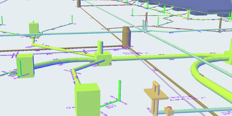
Image at top: This 3D model is of wet utilities for conflict detection on a local project. The H&A software reads alignment data created during design to directly create and update the 3D pipes, eliminating the need to produce a part-based model.