This article coincides with the December 2014 xyHt print article, Transformation of Observations – Part 2.
In the September 2013 issue of Professional Surveyor is Dr. Charles Ghilani’s excellent article entitled “Grid versus Ground.” The article demonstrates the error created by ignoring elevation in traverse computations and describes the numerical and logical errors inherent in processes that attempt to convert State Plane coordinates to ground coordinates.
Many surveyors use custom, or low-distortion, projections (LDPs) to make calculations on a projection grid that closely matches the ground. Properly done, this procedure provides ground coordinates that are rigorously referenced to a specific ellipsoid.
The data in “Ground versus Grid” provide an opportunity to compare the linear closure of a traverse computed on both a low-distortion projection surface and a State Plane projection surface (SPCS). Such a comparison provides valuable insight into the workings of plane surveying systems.
An LDP is not a simple localization with arbitrary initial coordinates. Instead, it is a coordinate plane whose defining constants are computed using those of a reference ellipsoid and appropriate mapping formulas. LDP coordinates can be converted directly to latitude and longitude, and latitude and longitude can be converted directly to LDP coordinates.
Figure 1 is a two-dimensional view of a raised plane and a secant plane. For clarity, the ellipsoid in the figure has eccentricity 0.50 compared to 0.082 for the GRS 80 ellipsoid. Note that the two planes are parallel to each other and perpendicular to the line normal to the surface of the ellipse at the central latitude for the projection. Either plane can be viewed as moving up or down along the normal. Thus, the raised plane can be created by raising the secant plane, or the secant plane can be formed by lowering the raised plane. Revolving the figure about the vertical axis will create a conic projection.
Figure 1. Two parallel projection planes
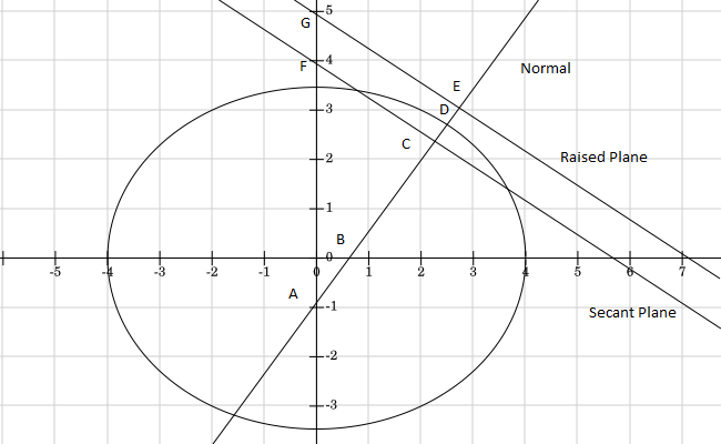
The natural origin of any projection plane is the intersection of the normal to the plane and the ellipsoid. In Figure 1, Point D is the natural origin for both the secant plane and the raised plane.
Scale factors at the natural origin are ratios of distances along the normal. For the secant plane in Figure 1, this scale factor is the ratio of AC to AD, and, for the raised plane, it is the ratio of AE to AD. Segments CD and DE are the ellipsoidal heights at the natural origins of the secant plane and the raised plane, respectively.
The mapping radius for the secant plane is CG and the mapping radius for the raised plane is EF. Triangles ACG and AEF are similar right triangles, making the lengths of their sides proportional. When a mapping surface is raised or lowered, the lengths of all three sides change proportionally.
The defining constants for the Pennsylvania Traverse LDP appear in Table 1, alongside those for the Pennsylvania North (Zone 3701) SPCS. While the differences are apparent, it is important to remember that the LDP constants are developed using the same formulas and processes as were used to develop Zone 3701.
Table 1. Defining constants for the PA Traverse Low Distortion Project

The PA Traverse LDP is first defined as a secant plane with standard parallels at 41° 17’ North and 41° 18’ North latitudes. These constants determine the latitude of the central parallel, the parallel of the natural origin. At its natural origin, this projection plane is about 7 centimeters below the GRS 80 ellipsoid. In comparison, at its natural origin, the Pennsylvania North plane is about 276 meters below the ellipsoid.
Ellipsoidal heights are given in “Grid versus Ground” for each of the traverse points. The average of these heights is about 530 meters. The length of the normal (Rn ) to the ellipsoid surface at the natural origin of the LDP is 6,387,453.8960 meters. These two numbers are used to calculate the scale factor at the natural origin, using Formula (1).
Formula (1)
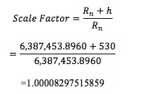
The scale factor and the normal are then used to calculate the corresponding Lambert conformal mapping radius, preserving the relationship between these two constants. The plane projection surface is raised from a few centimeters below the ellipsoid to 530 meters above the ellipsoid.
A note for plane surface purists might be in order here. Scale factors are derived from the geometry of the plane, the ellipsoid, and the normal from the vertical axis to the ellipsoidal surface. Elevation factors, on the other hand, derive from the connection between elevation and gravity. The Earth’s center is the gravitational attractor and the endpoint of any elevation measurement.
Because scale factors and elevation factors are based on different origins and paths to the ellipsoid surface, a plane projection surface cannot be raised by the same amount relative to both quantities. Consequently, the combined factor cannot generally be exactly 1 at points above or below the ellipsoid. Fortunately, the difference is usually insignificant and either can be chosen for defining the amount the plane is to be raised.
The constants for the initial secant plane are calculated using the formulas given in NOAA manual NOS NGS 5. The formulas used to calculate the scale factor and mapping radius for the low distortion plane do not appear in that publication, but they can be derived from the formulas that do appear there.
State Plane coordinates are given in “Grid versus Ground” for the beginning and ending traverse points. Latitude and longitude for these points can be calculated using the NGS Geodetic Tool Kit. As shown in Table 2, the longitudes of these two points are within a fraction of a second of each other.
Table 2. Data for beginning and ending points for the PA traverse, SPCS Zone 3701

The geographic coordinates indicate that Station 12 is almost due north of Station 2, but the eastings of the two points are about 152 feet apart. This difference is a function of the convergence correction required by the state plane projection.
The longitude of the beginning point (Station 2) was chosen as the central meridian for the LDP. Choosing the longitude of either point as the central meridian for this particular LDP makes convergence at the ends of the traverse essentially zero, eliminating the need for convergence corrections to the azimuths at the beginning and ending azimuth marks.
The LDP coordinates for Stations 2 and 12 are presented in Table 3. The eastings of the two points differ by about 7 feet, reflecting the near-zero convergence on the LDP surface.
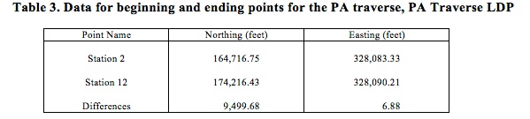
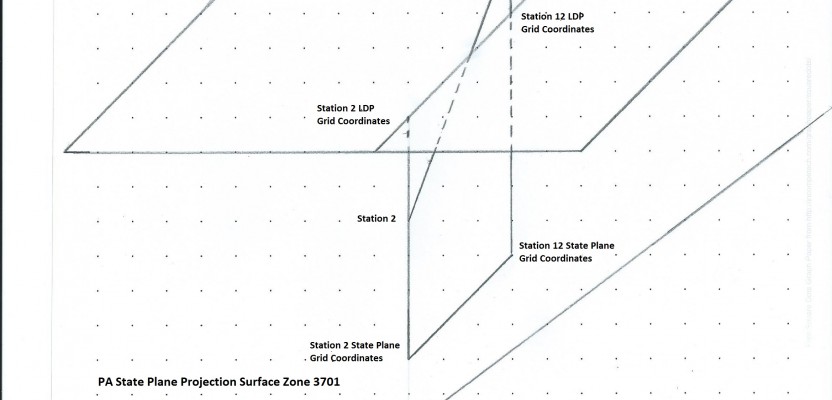
Figure 2 illustrates the difference in convergence between the two projection planes. Station 2 is on a meridian that is about 75 miles to the east of the central meridian of the State Plane projection surface. A line perpendicular (normal) to the ellipsoidal surface at this point will not be perpendicular to the State Plane surface. In contrast, because the Station 2 meridian was chosen as the central meridian for the LDP, a normal to the ellipsoid is also perpendicular to the LDP projection surface.
Figure 2. Traverse beginning and ending points on the LDP and State Plane surfaces: The LDP surface is above Station 2 and below Station 12, while the State Plane surface is below both points. The two projection surfaces are not parallel, although they are nearly so. The projection on the State Plane surface is skew to the one on the LDP surface because of the different north orientations of the two surfaces.

Table 4 contains the traverse computations using the LDP projection surface. Azimuths have been adjusted for the 12-second angular misclosure in the original data. The distances are ground distances.
Table 4. PA Traverse LDP traverse computations
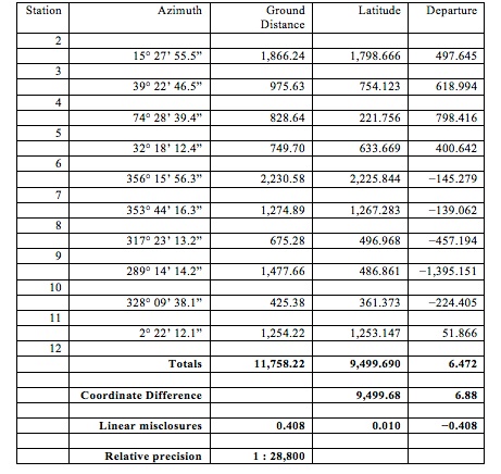
In “Grid versus Ground,” relative precision using observed distances and grid azimuths is 1:9,400. Using grid distances improves this figure to 1:36,000. This level of precision requires reducing both azimuths and distances to grid.
The LDP precision is roughly comparable with no reduction to grid. However, each point has a scale factor, an elevation factor, and a combined factor on the LDP grid. Using combined factors to reduce points to the LDP grid improves relative precision to 1:35,800. Fully-adjusted LDP data and fully-adjusted State Plane data produce virtually identical results.
This should not be surprising since both grids are plane approximations to the same ellipsoid. The grids are equivalent in the sense that each can be rotated and translated into the other. When the same field data are fully reduced on both grids, the relative precisions are the same.
An LDP offers the advantages of smaller convergence corrections and high relative precision without adjusting distances to grid. The price of these advantages is more upfront work and, perhaps, a less certain trail for surveyors following in the footsteps.
State Plane offers the advantage of a reliable published coordinate system that provides consistent results throughout a zone. The price is more backend work and the possibility of confusing grid and ground distances and azimuths.
As the example shows, however, neither is inherently superior to the other.
Figure 1 courtesy of FooPlot