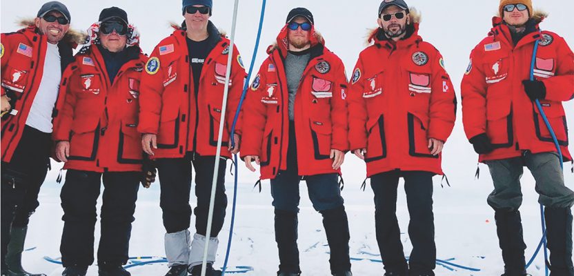
Above: From left – Jim Salazar, Mario Carnevale, Ken McBride, Myles Danforth, Alexey Dobrovolskiy (the author), and Janis Kuze.
An international research team used new UAV and GPR technology to locate a lost U.S. airplane 300 feet below the ice in Greenland.
On July 4, 2018, at Greenland’s Ice Cap, Jim Salazar and Ken McBride from Arctic Hotpoint Solutions and the Fallen American MIA Repatriation Foundation (FAMIARF) located the P-38 “Echo,” a U.S. dogfighter lost during the events of WWII. A subsequent hydraulic oil probe confirmed the plane’s location, bringing this part of a long mission to a gleeful close.
The mission’s success can be attributed to two factors: testing new unmanned-aerial-vehicle (UAV) and ground-penetrating radar (GPR) research technology and a team of skilled experts. Jim and Ken were joined by U.S.-based specialists Mario Carnevale and Myles Danforth from Hager GeoScience Inc., Latvian UAV expert Jãnis Kuze, and me (Alexey Dobrovolskiy, CTO of SPH Engineering).
Jim contacted SPH Engineering to join the search back in 2017. During this mission, our team battled Greenland’s snow storms, low temperatures, near-blinding Arctic sun, no internet, and technical difficulties in order to locate the lost airplane and set in motion bringing it home.
The Lost Squadron
On July 15, 1942, eight planes—six P-38 fighter planes and two B-17 bombers—left a U.S. Army base in Greenland to support the Allied war effort in the British Isles. Due to adverse weather conditions, the squadron attempted an emergency landing on a glacier far from populated areas. All the crewmen were rescued nine days later, but their planes, which were only lightly damaged during the landing, had to be left behind on the glacier. As time went by, the abandoned aircraft sank farther into the ice and could no longer be seen.
There had been talks of locating the legendary Lost Squadron ever since the Greenland Expeditionary Society recovered a lost Lockheed P-38F Lightning 41-7630 from under 260 feet of ice during the 1980s and early 90s. By 2011, radar technology helped establish the approximate location of “Echo”, a Lost Squadron plane piloted by Lt. Col. Robert Wilson in 1942.

Lt. Col. Robert Wilson
Locating “Echo”
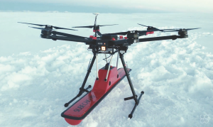
A drone carries a GPR across Greenland’s glacier during the search for a missing U.S. WWII plane.
For the eight-day expedition on Greenland’s Ice Cap, the team worked in two groups: the UAV group and the land survey group. The UAV team began their research with new technology, a GPR and a drone integrated system, to locate the P-38.
The UAV radar’s contact was confirmed by the ground surveying group—acquired data showed anomalies at a depth of around 300-340 feet. The distance between the determined locations of both groups was 10 feet, and the drilling location was calculated based on joint surveying data.
The moment of success for the expedition came in the form of a red fluid extracted from a depth of 340 feet, identified as the hydraulic fluid used in U.S. aviation.

Discovered hydraulic fluid
Experience gathered during the expedition confirmed the applicability of modern technologies to search and locate deep targets buried under glacial ice.
“We are confident that this innovative technology will assist our upcoming projects with the search of the USCG J2F Duck [with three fallen veterans] in the 2019 expedition,” said Salazar, director and founder of the FAMIARF.
The overall results were promising and proved that the performance of aerial surveying is ten times more effective compared to ground surveying and less risky for ground operators. Furthermore, putting our drones to the test in the harsh environment highlighted some equipment’s inability to function as expected, which is invaluable knowledge for future expeditions.
Arctic Hot Point Solutions is now organizing the excavation of the found P-38 Echo (to be conducted in 2019) and is continuing their search for other U.S. aircraft lost in Greenland.
GPR and Drone Integration
Due to Greenland’s hostile weather conditions, radar search was limited, and ground operations needed to be executed quickly and precisely. This is where our extensive unmanned-system-integration and software-development expertise was required; at SPH Engineering, we fly and test all things drones, small planes, and helicopters at our air-field on a daily basis.
Drone-Flying Tests in Latvia
 In order to expedite and ease search efforts, we integrated GPR and a drone into a single system, which enabled it to conduct fully automated glacier surveillance and produce precise location determination even in difficult-to-access or fully inaccessible areas.
During the expedition, it quickly became apparent that the GPR/drone integrated system was efficient in locating objects under deep layers of ice. The data obtained even in unfavorable weather conditions was precise enough for the mission purpose, saving the team time and effort.
The GPR-drone system was collecting data fully automatically, with flight and radar status monitored using UgCS (universal ground control software). In contrast, the expedition group using a GPR mounted on a sled had to be at least three-strong: one expedition member had to spearhead the group to check ice safety, another had to pull the sled, and the third had to move the control module.
GPR is a proven geophysical investigative method with a variety of applications, including geological surveys, buried-object detection, and freshwater bathymetry. To this day, the most common approach is to mount a GPR antenna onto a cart or a sled, towing or pushing it. This approach is labor-intensive and can be dangerous for field personnel, especially in harsh environments where such surveys are in high demand.
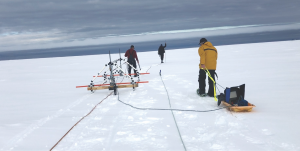
The ground group surveyed with GPR mounted on a sled, which required three people.
In some cases, GPR can be towed by a car or even mounted on a helicopter, but these methods have limited applications; a car would be commonly used for road profiling, while a helicopter would be used for applications where precision isn’t extremely significant, measuring ice glacier thickness, for example. Additionally, helicopter costs and flight risks in low altitudes are limiting factors of such an approach.
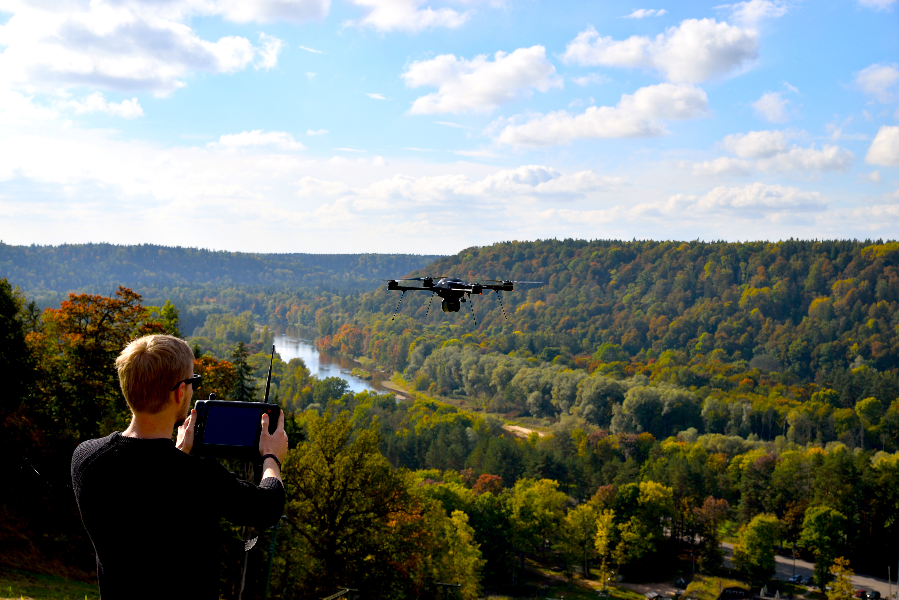
Janis Kuze prepares the drone for flight with GPR.
GPR/drone Benefits
Significant benefits of GPR/drone integration are varied. First, a drone is independently flown across the terrain with constant speed, improving fieldwork productivity tenfold.
Second, drones follow survey lines precisely. While it’s common to mark a survey area using flags or ropes, a drone can automatically follow pre-programmed routes with extreme height precision. Mounting a standard GPS receiver on the drone will provide the precision of approximately 3-4 meters, whereas using an RTK GPS will improve precision by mere centimeters. Additionally, an RTK receiver only increases drone-related expenditures by a few hundred dollars. A drone also remains at a constant speed, which can be crucial for continuous data-recording sessions; what is almost impossible to achieve using standard equipment is almost a free drone benefit. The last perk of using drones is as crucial as it is obvious: safety. In some cases, like our glacier mission, walking on the surface can be extremely dangerous. A drone operator is able to remotely monitor flight and GPR operations from a safe distance.
Our Custom System Putting together a GPR drone for missions such as Jim’s isn’t easy, but it’s not rocket science either. You need to fix a light GPR antenna under a drone and use a standard tabled computer (also fixed somewhere) to record data.
Although such a system will work in ideal conditions, you still need an integrated system to reap the real benefits. A fully integrated GPR/drone, like the one we used for the mission, has the following features:
- GPR data is recorded onboard using specialized data-acquisition software that will not require the operator’s intervention to start/stop logging and can work robustly in unattended mode.
- GPR data is geotagged using GPS coordinates (every trace is recorded together with coordinates).
- If the drone is equipped by RTK GPS, precise coordinates should be used to geotag data.
- The drone operator is able to control GPR from the ground: start/stop data recording, change GPR mode and settings, etc.
- The drone operator should be able to see how GPR works or at least see current trace data.
At SPH Engineering, we developed this integrated system.
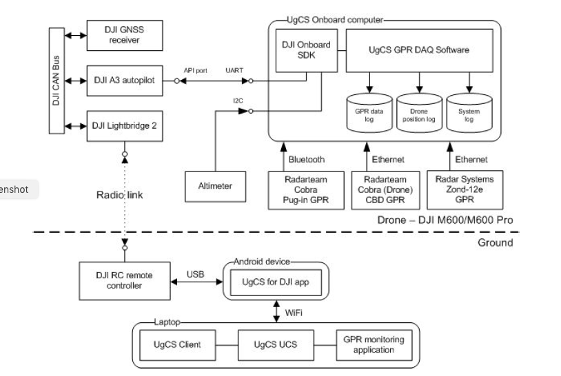
The architecture GPR/drone integration.
Although it currently supports only three types of GPR systems (Radarteam’s Cobra Plug-In GPR, their Cobra CBD GPR, and Radar Systems’ Zond-12e), support of new radars is under development.
Our team used two drones to locate the aircraft: one to carry the GPR and a second for filming and scouting. Arctic Hot Point Solutions later commented that, “the performance of this rig was truly amazing and no doubt will become a very viable solution for many GPR applications that require large-area surveys or difficult terrain that would make a conventional surface-towed system impractical.”
Operational Tech
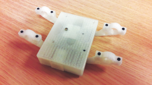
The data-logging computer is ready for mounting in its 3D-printed case.
The onboard computer used to integrate GPR with a drone was a single-board Linux computer with industrial temperature operating range. The computer was assembled inside a small and light plastic box that can be fixed under the drone’s hull. The computer’s primary role was to help combine data from GPR and autopilot, store the data on an SD card, and support communications with the ground station.
- The onboard computer had three interfaces: interface for GPR (it can currently be Blue tooth and wired Ethernet),
- interface for an autopilot, and
- interface for ultrasonic/laser altimeter.
Bluetooth is very popular for compact GPR systems like the Radarteam Cobra Plug-In GPR, and its interface makes it possible to quickly integrate such radars without modifying their electronics or software.
However, it’s not the ideal solution because of possible interference with the drone’s radio link, which uses the same 2.4 GHz frequency as Bluetooth. To minimize the risk of interference, a special “Bluetooth cable” was made to connect the data logger computer with GPR: two small 2.4 GHz antennas fixed in close proximity to each other. One antenna should be connected to the Bluetooth port of GPR, while the second antenna should be connected to the port of the data logger computer. We conducted multiple tests in order to optimize this design and prevent future interference and data loss during surveys.
Ethernet is the preferred interface—it is protected from any interference from other radio equipment on the drone and is much more robust. This interface is used to connect radars like Radar Systems’ Zond-12e GPR system.
The onboard computer receives a stream of drone attitude information from the autopilot, most importantly the drone coordinates. These coordinates are used to geotag traces received from the GPR. If a drone is equipped with RTK GPS, receiver data will be geotagged with centimeter-level precision.
Drone coordinates to geotag GPR traces
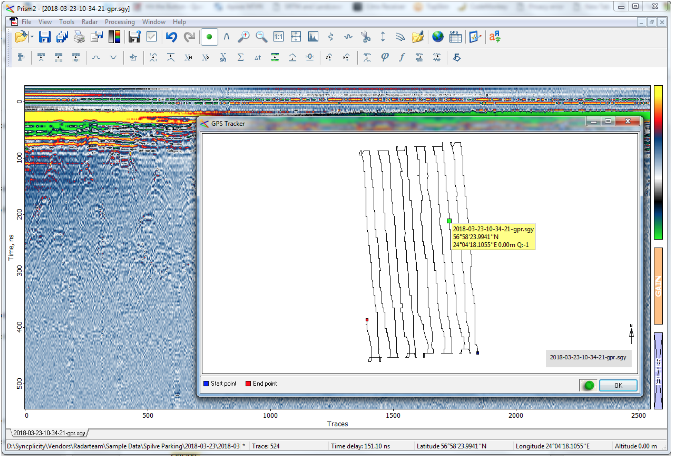
Geotagged data is then recorded in SEG-Y format, which is standard for storing geophysical and GPR data. Because original SEG-Y format was invented to store seismic data, it doesn’t have a standard field for storing coordinates of traces. Instead, we used one of the format extensions compatible with Radar Systems’ Prizm2 software.
Data logging is started automatically after take-off and stopped at landing. The same autopilot interface is used to send the system status to the ground station, allowing the drone operator to see what’s going on with GPR, to start/stop recording manually, and to perform other commands.
Using UgCS
UgCS is for central management of all types and manufacturers of unmanned vehicles, enabling the control of one or a fleet of drones on a single mission in multi-operator mode and multi-platform environments.

UgCS screen with live GPR data on the right side
The ground control software helps support operations and communications with drones and GPR.
UgCS is in charge of the full survey lifecycle, from planning to flight completion. It also provides the communication backbone for GPR monitoring applications: a window showing GPR status and current traces, allowing it to send the system GPR-specific commands (like start/stop data recording). This application also allows downloading recorded GPR data after landing.
Flight altitude over ground (surface) is a paramount consideration. For better results, a drone should fly at a very low altitude—below the length of the EM wave corresponding to the center frequency of GPR.
Technically, UgCS allows the planning of drone flights in terrain-following mode, but that requires a precise DEM (digital elevation model) uploaded into UgCS. And while different sources of data elevation exist (from free to commercial providers), there are still areas where it’s impossible to receive precise DEM, which is primarily due to the survey area’s fast-changing elevation (glaciers, mines, construction areas, and other factors).

UgCS screen with terrain following route
How to Use GPR on a Drone
Any sensor for a UAV requires a specific approach to plan a drone-survey mission. For example, when planning a photogrammetry mission, the camera’s parameters, GSD, image overlap, and other information is vital. Sophisticated mission planning software will require these values to generate a flight plan and guarantee data acquisition of necessary quality.
The same applies to GPR, which can become a complex process because GPR can be used for a wide variety of operations: soil layer profiling, utility mapping, underground target search, and others.
Common Considerations
Flight altitude: The common rule is to always fly as low as possible. The best results will be obtained with the altitude being less than the EM wavelength (in the air) corresponding to the GPR center frequency.
Potential customers often like to know whether it’s possible to use the drone with GPR if the survey area has trees or other tall vegetation. The SPH Engineering team has spent considerable time conducting test flights at relatively high altitudes (20m and even more) and concluded that the gathered data from such an altitude was nearly useless.
A sample of GPR data gathered from 45-50 meters altitude. Reflection from trees and the surface is clearly visible, but nothing useful is shown to be underground, despite caves located in the surveyed area.
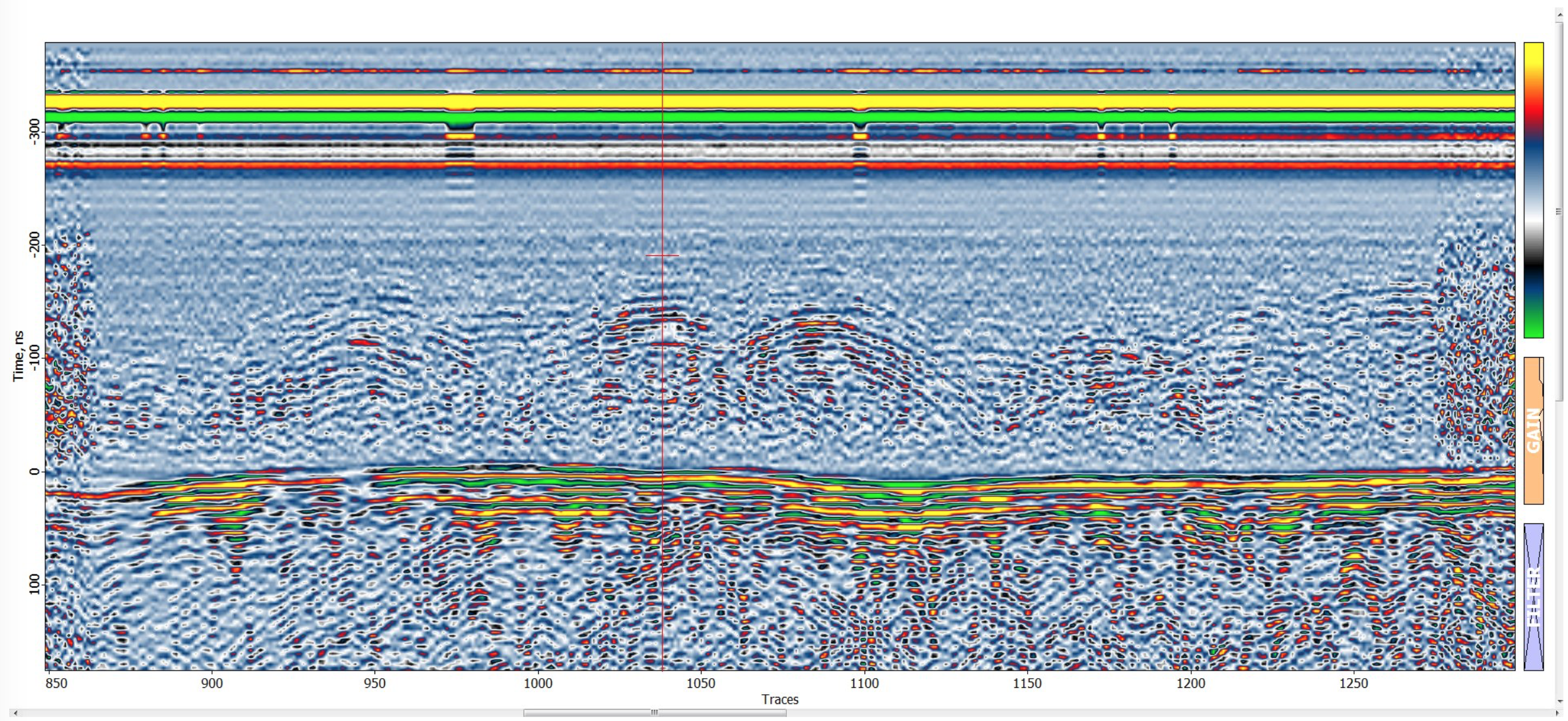
Reflection from trees and the surface
A simple formula can be used to calculate the recommended altitude (or wavelength in the air) in meters:
Altitude = 300 / [GPR center frequency in MHz]
For example, recommended altitude for 100 Mhz is 3m.
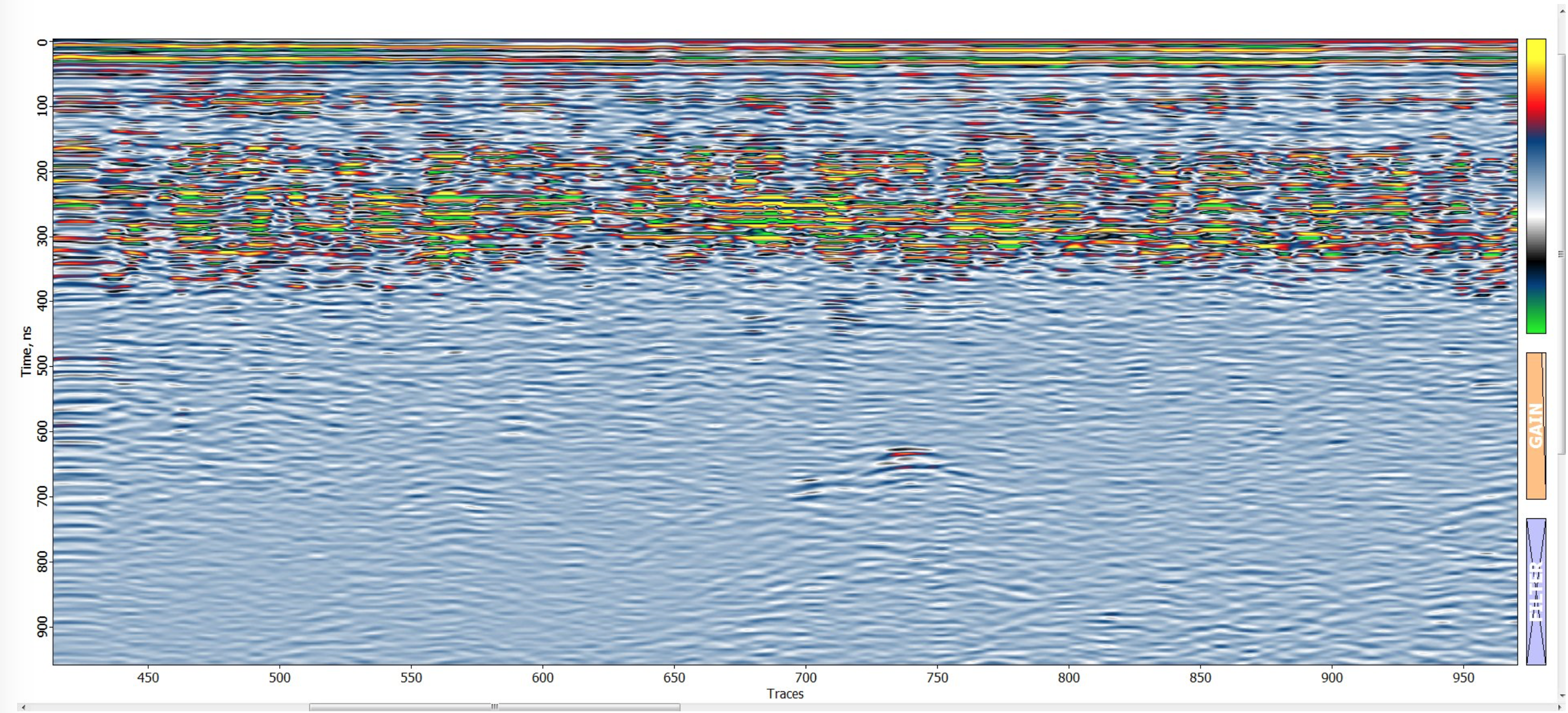
Flight speed: A common rule is to fly as slowly as possible. But this consideration may conflict with drone overall flight time and productivity of field work. In the online version of this article are images of data obtained at the speed of 2m/s (with the altitude being 10m; the location is a glacier in Greenland). Despite the high flight altitude, data is clear and displays an anomaly under ice.
The same area was captured while flying at 10m/s and the data shown seems noisy and useless.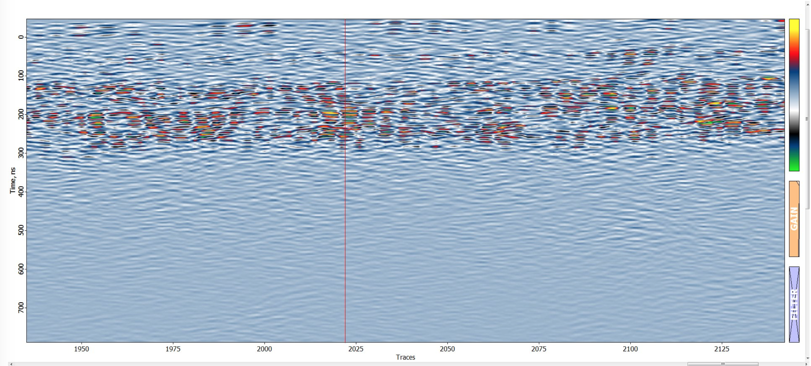
The main reason is the chaotic drone fluctuations at high speed. GPR’s antenna is of a substantial size and produces serious air drag at high speed, causing drone oscillations. We suggested and used our drone and Radarteam’s Cobra Plug-In GPR antenna at the maximum speed of 3m/s. For maximum data quality, we advise flying even slower, at 2m/s or even 1m/s.
The second factor in selecting flight speed is related to the number of traces per second. The hi-end Cobra Plug-In GPR produces only 5-6 traces per second because it implements internal stacking. Needing to detect or map a target of a 1m size will require at least two to three traces with the drone being over the target. This would mean limiting the speed to 2m/s. For soil layer profiling missions or a large target search, 3m/s should do the trick.
Wind speed: As stated previously, drone oscillations tend to produce noisy and even useless GPR data. Wind speed and gusts are limiting factors for GPR drone operations, with a speed of 5m/s or above rendering all work useless. The best results are achieved during calm weather.
Survey lines overshot: At the beginning and end of each survey line the drone will accelerate and slow down. During this time, the drone will oscillate slightly forward (and a little bit in a perpendicular direction after a U-turn). Acquiring clear data requires extending the survey lines beyond the designated survey area. In UgCS we use the Overshot option for AreaScan segments.
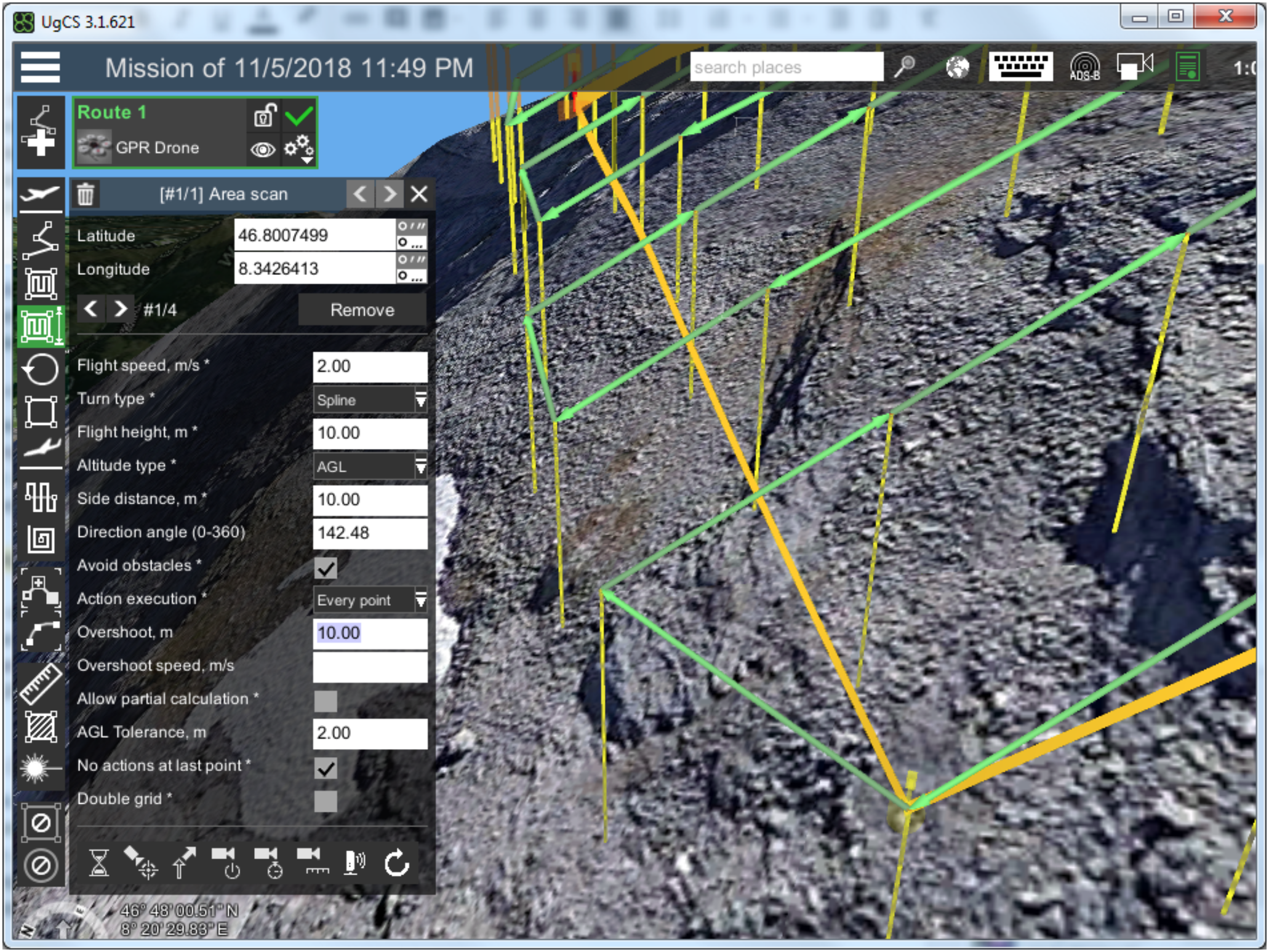
AreaScan with overshoots 10m length.
The overshot length can be estimated using a simple formula: 5m x [flight speed]. For example, those using a speed of 2m/s on survey lines are recommended to use a 10m overshot. This distance will be enough to accelerate and stabilize drone attitude even with such heavy payload as GPR.
The distance between survey lines: Those looking to detect particular targets or map underground objects will want to detect this target from at least two parallel survey lines.
To achieve this, the distance between survey lines should be equal to a radar’s “footprint” on the estimated depth of buried targets. A radar’s footprint can be estimated using Fresnel equations:
Fresnel radius: r=/4 + √(depth*/2)where is an EM wavelength in a medium.
However, drone GPR operation calculations are more complex due to the EM signal propagation in at least two mediums: in the air and under the surface. To help with this, our engineering team developed a special calculator.
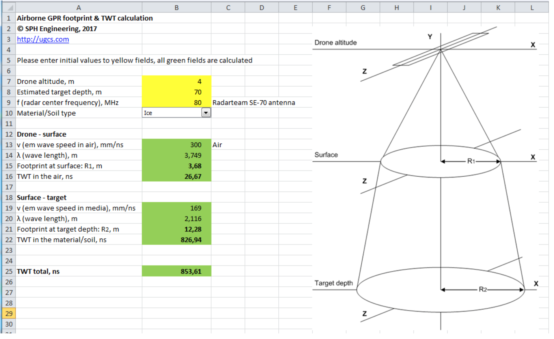
GPR/drone footprint calculator
By entering the center frequency of the GPR antenna, drone altitude, estimated target depth, and the soil type, the calculator will display the radar’s footprint on the given depth.
Data interpretation: Even for standard survey methods, GPR data interpretation can look like magic, but experienced drone-data analysts will consider additional factors. Our engineering team has prepared data samples that are online; source data in the SEG-Y format can be obtained by request from ugcs@ugcs.com.
Useless data: Data gathered using GPR during particular parts of the drone’s trajectory will be useless, including:
- during turning points,
- when a drone accelerates/brakes,
- when a drone is changing its altitude, and
- in case the altitude is too high.
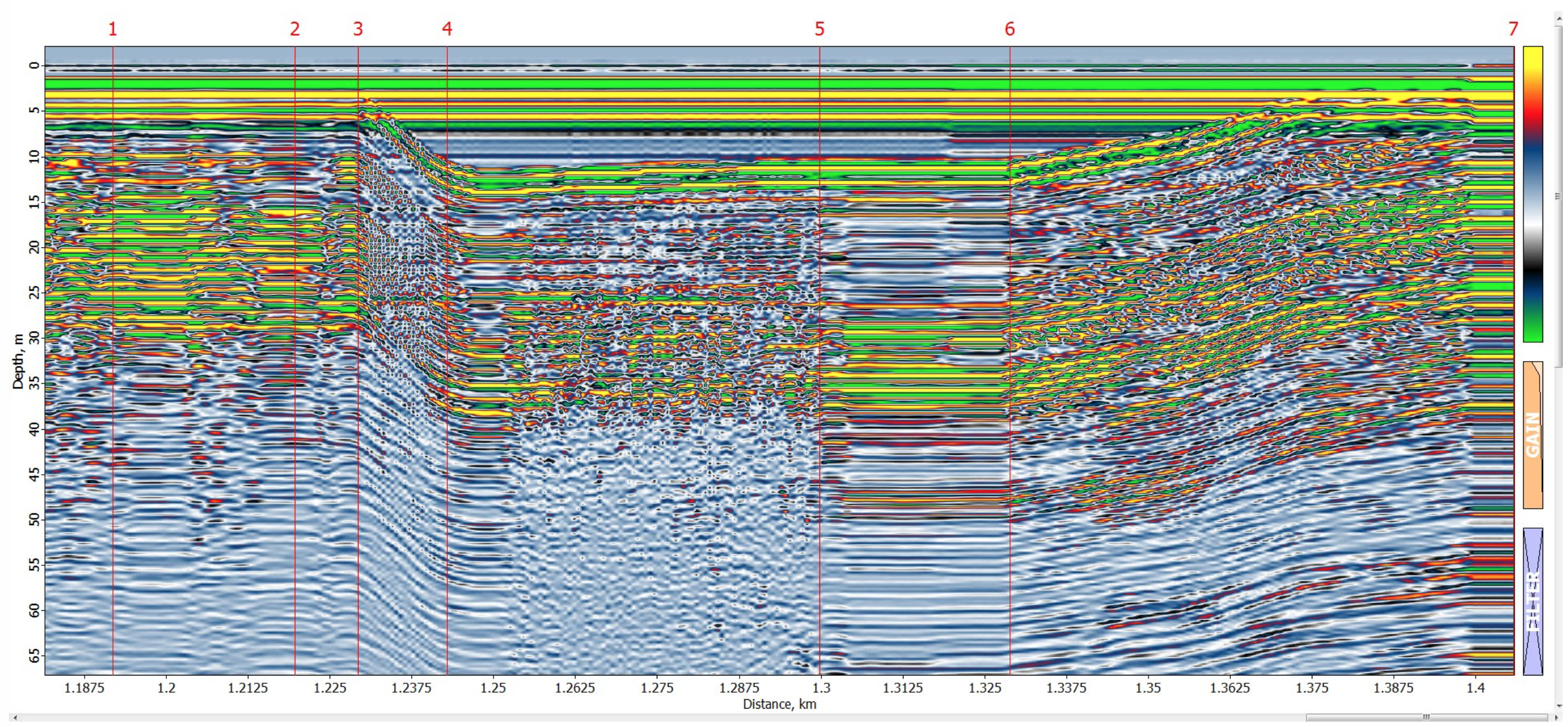
Example of useless GPR data.
1 – turn point
2 – one more turn point
3 – drone climbs from 4 to 20 meters
4 – drone accelerated to 10m/s
5 – drone brakes and stops
6 – drone descends until landing
Frozen lake bathymetry: A dataset was gathered over the ice-covered Svartbyträsket lake in Sweden. Because of a drone-operator mistake, the drone flew at a 20m altitude above the surface. Despite this, a surface reflection, a layer of thermocline and sediment can still be observed at the depth of up to 8 meters.
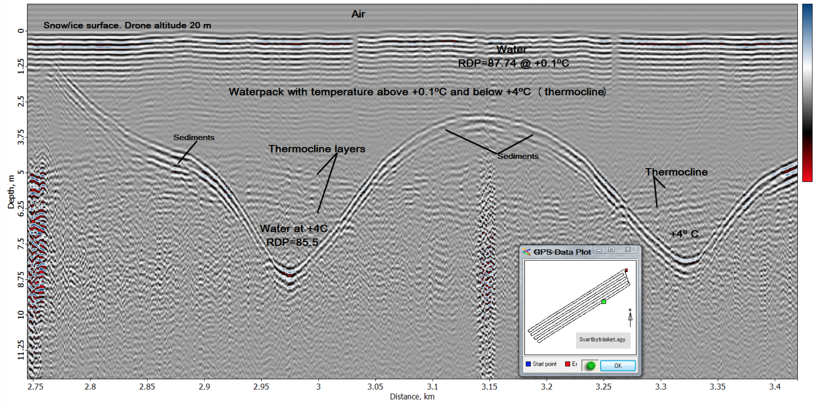
Frozen lake bathymetry
Data gathered in Greenland: Ice is nearly the perfect medium for GPR surveys. Unfortunately, there aren’t many applications in this environment. With the exception of exotic ones such as this mission, there is usually only one standard ice application: glacier bottom profiling. Areas without crevices will supply clear data containing almost no reflections from the middle of the ice.

Labels 1,2,3 are reflections from P-38 “Echo” fighter.
Unexpected Expedition Challenges
Weather
Greenland’s summer temperatures don’t usually exceed 10°C, so the team was not alarmingly cold. With the camp being erected at around 700m above sea level, it was often quite warm during the daytime, except for three days (out of eight) when everyone was snowed in during a snowstorm. Needless to say, it was below freezing during the night.
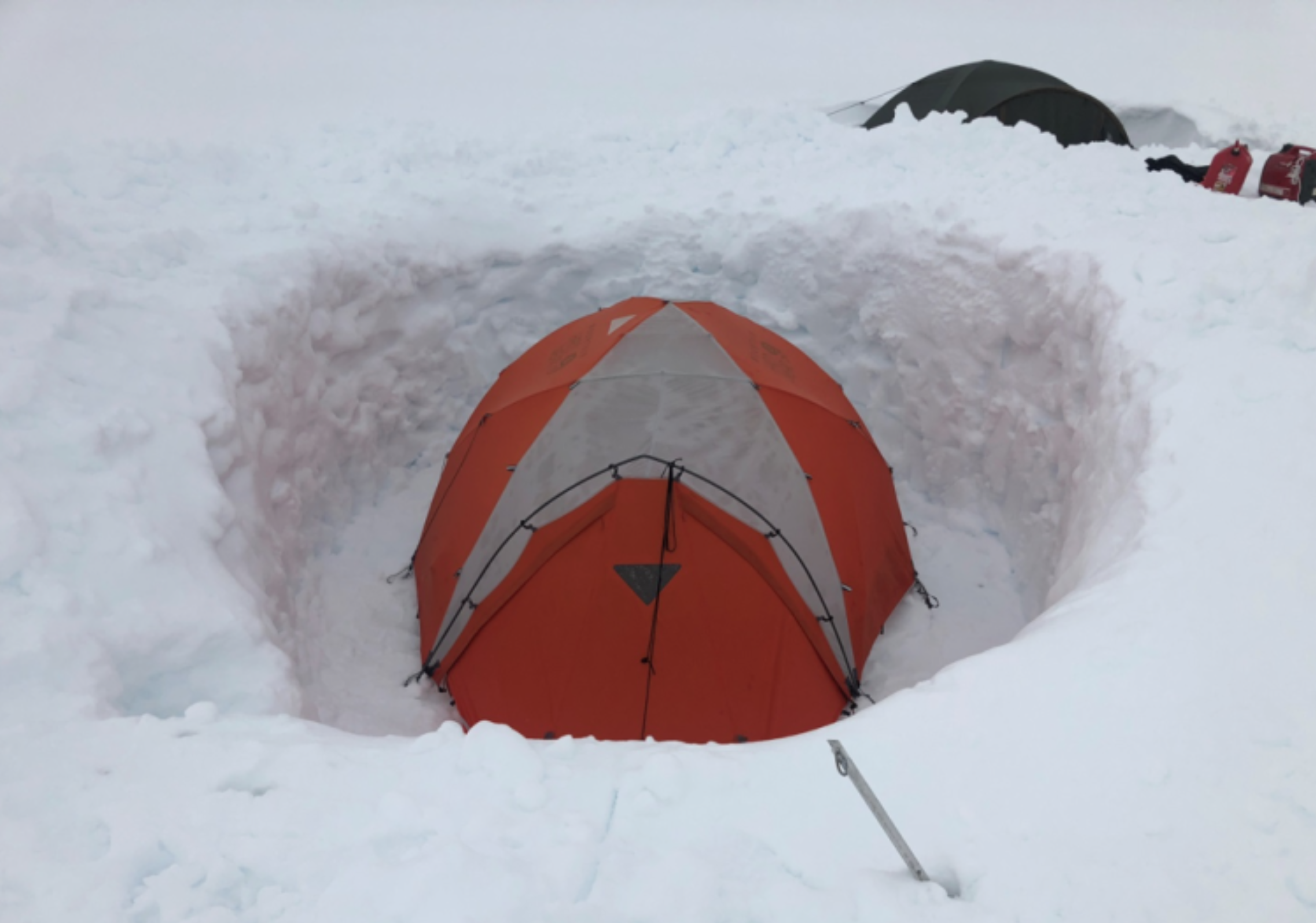
Tents snowed in after a snowstorm. Third day on the cap.
Although weather conditions didn’t affect the team, they did have unexpected effects on the equipment. A standard recommendation for using drones in such conditions is to keep your batteries in a warm place, but we didn’t have a single warm place on the ice cap. So Salazar, our expedition leader (and a real hero), once took two sets of M600 batteries into his sleeping bag for the night, but it was not very effective. I forgot to ask him how he slept that night.
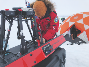
The bright Arctic sun was actually an even bigger problem. The light was coming from all directions on the ice cap; you feel as if you’re inside a mirrored chamber with 1000 Lm of light. Nothing was visible on screens outside, not even when the sun was masked by clouds.
The only comfortable place to work with laptops was inside our main tent, but that required close and constant coordination between the ground station operator sitting inside the tent and the drone pilot outside.

The team’s main operations tent. Batteries can be seen on the right. GPR data can be seen on the left side of the laptop screen, drone route in the center and drone telemetry on the right.
Altitude Drop
The team’s continued GPR/drone use raised another problem for low-altitude flights. Standard drones use barometric sensors for altitude measurement which are sensitive to external temperature and wind speed (because wind gusts will cause pressure variations inside the drone’s hull). Temperatures dropping quickly (common for areas like the Arctic, the Antarctic, deserts, and mountains) caused a measured altitude drop of up to 3-4 meters during a single flight. In some cases, the team had to stop the missions to prevent the drone from colliding with the glacier’s surface.
A special solution was developed to overcome this obstacle: an automatic terrain-following using ultrasonic/laser sensor. It allowed us to maintain a constant surface altitude with high precision (centimeters) assuring safe flights and quality data collection.
Collision Detection Sensors
We used a small drone for filming mission events for checking the safety of routes before sending an expensive system far off into the fog. In order to get useful data from the GPR, the maximum altitude from the ground could have been 10 meters, but the lower the altitude the more accurate the data.
We tried keeping an AGL altitude of 3 meters and used terrain-following routes generated by UgCS using ArcticDEM elevation data. However, we didn’t have full confidence in the DEM data precision, so when we were planning to fly far routes we decided to use a less expensive drone to test whether it was possible to fly the generated routes without colliding with the glacier surface. Online is an elevation profile of one of the flights down the glacier.
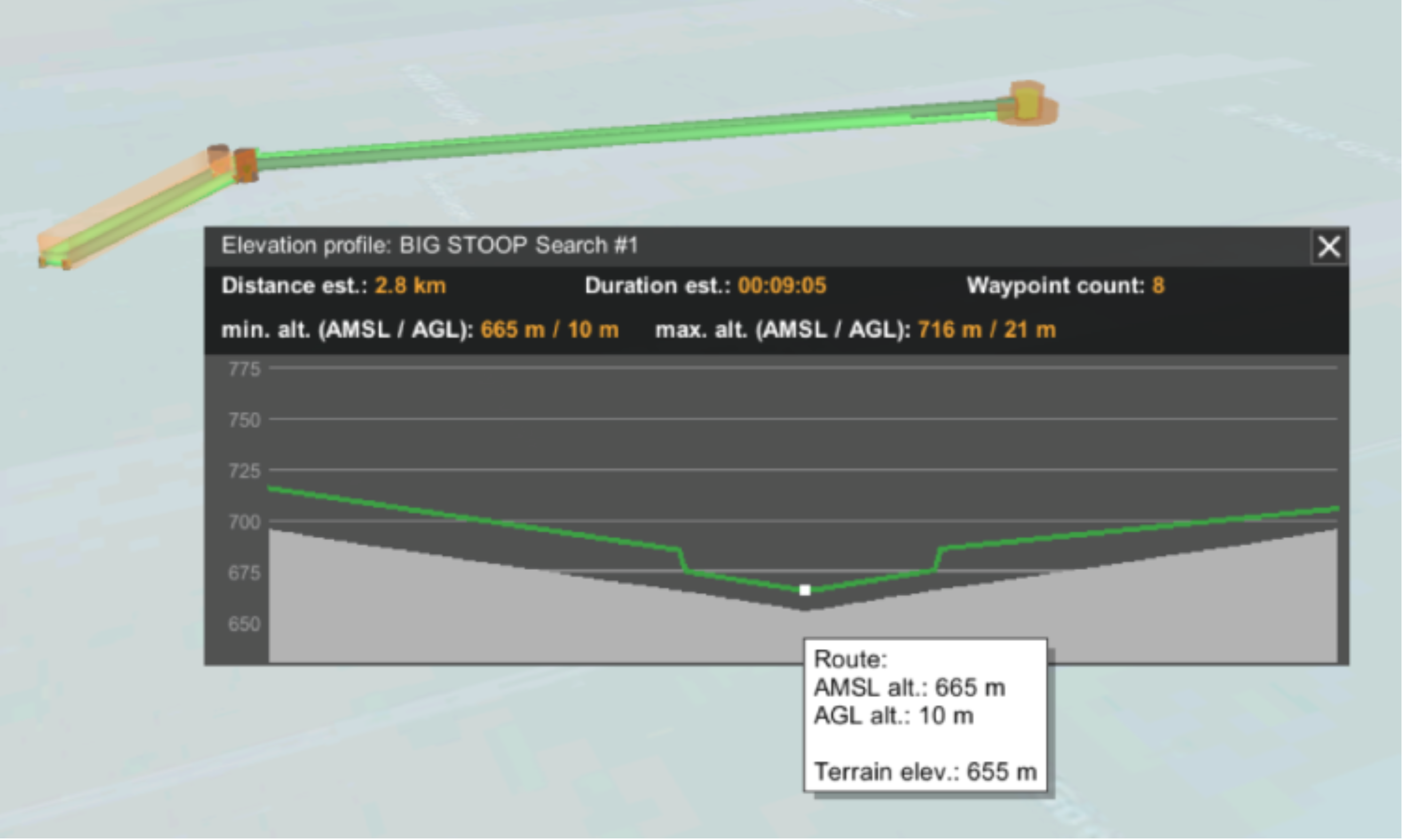
An elevation profile of one of the flights down the glacier.
The collision detection sensors and the drone algorithms were not only useless in such conditions (with everything being white and with the omnipresent fog), but it could have caused serious issues. For example, while on an automatic mission, it could detect an obstacle and stop. In case of any problems with the radio link, a drone could easily be lost.
From my observations, false potential collision detections can be caused even by very light fog or clouds, even with the drone itself being clearly visible. I, therefore, recommend disabling all collision detection sensors before flying in such conditions and relying on your eyes, brains, and piloting skills only.
Watch a short video about the Greenland mission at the UgSC channel on YouTube.