Complex roofing work with bent and twisted beams gets back on track thanks in part to construction verification software.
This $31 million construction project was complicated from the start. The site was in the Danish city of Ballerup, and the plan included five structural steel buildings that would comprise a new, state-of-the-art health care facility. None of the buildings would be identical: varying in size, shape, and height and having several curved walls. The major similarity among them was the steeply sloped, wooden roof covering each structure.
Per design plans, the steel skeletons of the buildings were built in the first phase, with the erection of 100 or more vertical, horizontal, and angled I-beams in each.
During construction, another sub-contractor was fabricating wood and more than 90 roof sections, called cassettes, at another location. The cassettes would be hoisted on top of the building frame and attached to the angled beams, forming the pitched roofline.
The number of cassettes varied with each building, and individual roof sections were carefully designed and built to fit precisely into specific places on the steel structure in accordance with the 3D design model created by the project architect.
The roofing subcontractor expected installation of cassettes to take about 20 minutes each as they were lowered into place and bolted to the appropriate beams.
However, problems were encountered roofing the first building. Some of the prefab cassettes required hoursÑup to a half dayÑto install because they didnÕt fit properly onto the steel structure. Crews had to manually cut the sections and make modifications to the structural beams themselves just to get the cassettes to lay snugly into position for attachment.
The delays set back the overall construction project by days and caused significant cost overruns in the roofing budget.
The general contractor realized the problem was likely related to inaccurate installation of the steel beams. And if the first structure deviated from the design model, the structure deviated from the design model, the other four buildings probably did as well. Construction was halted while the situation was studied.
Spotland, an engineering/construction services company located in nearby Kvistgard, was brought in to figure out what had gone wrong.
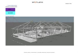
A scan of one of the buildings using a Faro Focus S 350; approximately 30 scans were made for each building.
Spot-checking the Structure
Spotland had formed as a surveying group within a larger construction firm and then spun out as a separate company. The company quickly began expanding into 3D scanning and modeling services, specializing in development of building information models (BIM), while also lending its expertise to major infrastructure development projects in Denmark and Sweden.
Spot-checking the accuracy of construction work is common, explained Spotland BIM engineer Martin Matti, and usually involves using a total station or manual measuring device such as a tape measure to determine if elements are in their proper locations and positions. The drawback to these techniques is they’re usually so time-consuming that just a small percentage of steel beams or other elements can be checked.
“The general contractor wanted to try something new and asked us to scan the steel structure,” said Matti.
The Spotland team used a FARO laser scanner to capture 35 scans in the remaining four structures, which had no roof, MEP (mechanical, electrical and plumbing) systems, or architectural features installed.
After registering the scans and creating separate point clouds for each building, Spotland imported the as-built models into Autodesk Revit software for comparison with the 3D design model.
“We let the general contractor know [that comparing the as-built to the design model] was not a regular service, and we considered it a test,” said Matti.
Revit is not designed to digitally compare two models, which meant the Spotland team had to visually inspect the overlaid models to see if there were deviations between the steel structure and the design plans. They found two areas in the as-built model where the actual steel beam locations deviated significantly from the design.
While this confirmed that the roofing problem likely resulted from incorrect beam installation, project participants suspected the deviations were more numerous than could be seen with the naked eye.
Digitally Checking Beams
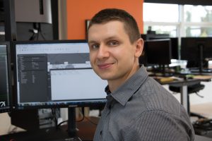
Martin Matti is a BIM engineer for Spotland.
A Spotland colleague remembered a demo he’d seen of an automated construction verification software called Verity, conducted by its developer, ClearEdge3D Inc. of Virginia, at a trade show. Several years earlier, ClearEdge3D had introduced EdgeWise software products, which use algorithms to automatically identify, measure, and model architectural, MEP, and structural features in 3D point clouds. The firm had enhanced many of the same algorithms to create the Verity automated construction verification package.
“ClearEdge3D was looking for beta testers, so we signed up and tried it in the Ballerup project,” said Matti.
The Spotland technicians imported the point cloud for the first scanned building structure into Navisworks, where a plugin integrated Verity into the workflow. For digital comparison, a CAD file was obtained from the company that supplied and installed the steel. This company created its own CAD design of the steel skeletons based on engineering documents provided by the project architect.
Verity allowed Matti to select and input deviation parameters for analysis. He chose 10 mm, which meant the software would analyze the as-built placement of each steel element in the point cloud and compare it against the CAD design. Any element out of tolerance by more than 10 mm in the x, y or z axis would be flagged.
The software even inspected the steel beams for twists, sags and curves not matching the design.
“We set up the software [to analyze the first building], went to get a cup of coffee, and it was done when we returned,” said Matti. “Analysis took about 10 to 15 minutes.”
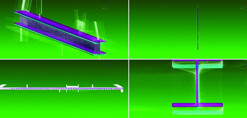
The software generated tabular results showing analysis metrics for each element. These could be queried to see details of measurements along each axis and degree of twist or bend with any OOT results highlighted. The analyses were also displayed as a colorized point cloud in Navisworks with colors indicating elements: In Tolerance, Out of Tolerance, or Not Found.
“About 70% of steel beams [in the first building analyzed] were out of tolerance,” said Matti.
Nearly all the deviated beams were among the angled ones that joined together forming the roofline. Some beams deviated from their designed positions along all three axes, but particularly alarming was the fact that several of the roof beams were bent in the middle and twisted at their ends, as if they had been forced to fit in place during installation. The bends and twists were not called for in the CAD design.
Initial reviews of OOT elements in the first building indicated a third needed closer inspection onsite, with eight beams possibly requiring remediation. Those beams with severe deviations might have to be replaced entirely or, in the case of the bent beams, be buttressed from below with another element. Those decisions will ultimately be made between the general contractor and steel subcontractor.
Analysis of the second building revealed a similar number of OOT steel elements, indicating the installation problems were replicated in all the structures. The third and fourth structures are being analyzed as of this writing.
The Future of Verification
The initial results of the Verity analysis have impressed the Ballerup general contractor so much that they have suggested incorporating the software into the routine workflow on a construction project as an accurate method of checking all installed steel elements in an erected structure before moving to the next construction phases.
On the Ballerup project, costly delays might have been avoided had the software been available to verify the proper installation of steel beams before the roofing phase began.
Spotland agrees with the general contractorÕs assessment and suggests taking those recommendations a step further. Based on its beta testing experience, Spotland believes the software should be used at multiple junctures in the construction process, such as at the completion of installation of architectural features and MEP systems. The software would find potential problems that could disrupt or delay the next construction phase.
Top image: One of many cases where Spotland used verification software to identify critical areas that had resulted in delayed installations of the prefabricated roof cassette system.
This article is part of the February 2018 magazine. Click on the cover below to view the other articles in the February 2018 issue of xyHt magazine.
