How multiple companies collaborated to solve persistent challenges to rapid comparisons of design models and constructed features—in high-precision 3D.
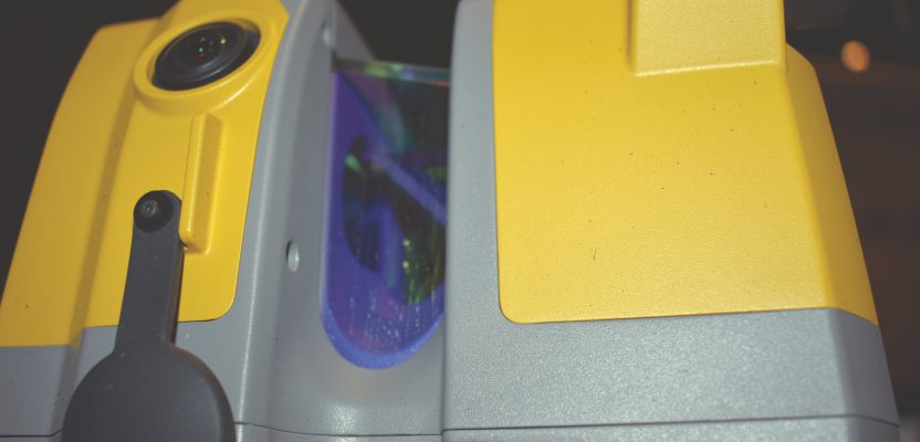
Image above: the GTL-1000 scanner.
When you look at the images in this article, if you see a piece of hardware and think this is a product review, you may be disappointed. It is an impressive-looking instrument, albeit a little odd.
Instead of looking at the hardware and wondering, “What can it do?”—let’s work backwards from “What do we need to do?” That will reveal a software workflow solution that precipitated development of the instrument. The real story is in the improved workflow and how it tackles a very real problem for BIM adoption.
The digitalization of construction and infrastructure development sounds good on paper, and while adoption has been slower than hoped, substantive progress has been made. At xyHt we’ve been examining the productivity enhancements that BIM can bring, but persistent challenges still need to be solved before the benefits can be fully realized.
One key challenge is in executing complete, precise, rapid, and cost-effective validations of constructed features when compared to design models. This is especially true for the complex structures that designers, and their clients, seem to be obsessed with, but also for other practical reasons. Customers demand energy-efficient and smarter structures, and this puts an additional premium on the complexity of models and the integration of pre-engineered elements.
Compare Despair
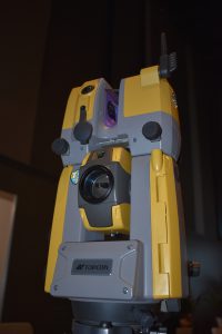
The GTL-1000 scanner sits atop a Topcon GT robotic total station and is operated via the same controller and field software.
Verification of constructed elements is often done with an array of devices that offer varying levels of precision: handheld lasers, digital tapes, handheld SLAM, total stations, spirit and digital levels, etc.—and conventional high-end scanners.
With any device (other than scanners), you are simply sampling: checking certain key measurements and hoping the rest of the structure is okay. With a high-end scanner you can put the cloud and/or modeled as-built surfaces into software to compare to the design model. Cloud, mesh, 3D surfaces: there are many workflows to choose from for verification, but there can be a lot of steps, prep work, and varied deliverables.
It has gotten easier to go onto a construction site with a high-end, million+-points-per-second scanner and rapidly scan the entire area of interest, but a bottleneck often forms back in the office. Ironically, folks who are tasked with comparing the as-built to the design model often have to decimate those mega-clouds to a manageable density.
Some existing scan-verification workflows might involve set up of control with a total station (or using a high-end scanner that does a rudimentary “traverse” or camera-based alignment). And while setting scanner targets has become mostly moot (with the advent of cloud-merge software), often you still have to do some amount of adjustment to get the scans to merge while maintaining a tight registration to control.
What if several of those steps could be streamlined or even eliminated? As the good old reliable total station still represents peak precision (in fidelity to the reference framework of a construction site), adding scanning to total stations has been recognized as highly desirable. Several amazing scanning total stations have been developed, but the scan rates are still somewhat limited.
The idea of a coaxial scanner on top of a total station has been tried before, but this time it looks to be in a sweet spot of resolution and range that meets the needs for BIM verification. And a companion workflow leads all the way to standardized reports that can be easily shared online with an entire team.
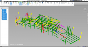
A view inside Autodesk’s Navisworks of as-built structural members, scanned with a Topcon GTL-1000, that has been identified via ClearEdge3D Verity as being at different levels of compliance to the design model.
Verity
“Verity is a tool that lets you take scan data and model data and check to see if the work is installed correctly,” said Kelly Cone, “so you can, for example, validate if a beam is in the right place and within tolerance.” Cone is vice president of industry strategy with ClearEdge3D (purchased by Topcon several years ago), and was heavily involved in the development of Verity.
Verity is part of a complete workflow that works in concert with Autodesk Navisworks (and therefore can be used for validations using standard design model types). It ingests cloud data from scanners like the new Topcon GTL-1000 that was purpose-built for just such a workflow. (But more on that instrument later.)
I got a demo of the workflow from Cone at the recent BILT North America event in Seattle in July of 2019. BILT NA is a conference and exhibition focused specifically on the digitalization of construction, BIM, and automation of related processes, and Verity and the GTL-1000 appeared to be hot topics at the event.
Cone said, “The beauty of this is that you have scans that are instantly on a control system. For regular QA/QC work, to shoot on the retros, prisms, etc., you need to get on the control, so this also puts the scans on that control. It is a simple and easy workflow, and it all pops right into the model.”
He said that in legacy workflows you might be using two or three different instruments and might have to register and align data after the fact. “We can take this out to the field and take a computer or laptop, take the scan off the instrument [via SD card], and in the field be able to check if all the beams and MEP, etc. have been installed correctly.”
Once you have the scan, or scans (full dome scans take less than two minutes each with the GTL-1000), you then port the data to the Verity package.
“Many GCs [general contractors] are using Navisworks. Verity puts the scans alongside the model geometry that is in Navisworks,” Cone said. “It takes the point cloud data, takes the model data, uses a couple of different computer vision algorithms to automatically parse that to determine if it has been installed to tolerance. And we provide lots of different types of reports to take upstream to the GC and the owner.
“Basically, it is showing how good of a job you are doing as a contractor or sub-contractor—and it can be done with a lot of automation.”
Cone says that GCs are looking for richer data in their construction verification workflows. “You can check everything rather than just spot checking, which is the big revolution of pairing this kind of tool [the GTL-1000] with our kind of software. And you get out of the old world of checking a few things and hoping that everything else is in the right place.”
For more specifics on data types and the Verity/Navisworks workflow, I spoke with Trevor McGough, an application engineer with ClearEdge3D.
McGough said, “As long as you can get that scan into [Autodesk] ReCap, then into Navisworks, you are good to go. Verity provides unique reports, has full integration with BIM Track, BIM 360, and Procore [popular information management packages for BIM]. If you are using any of those, you can put comparison data and reports out into the cloud or a central location for the whole team to access.”
Outputs and reports can include both graphic and tabular data. “Verity can produce heatmaps showing the differential between a scanned and a design model, colorized by a scale. This can include subtle deviations on steel, sags on pipes, floor levels; you can even export those to take back into Revit to show heat maps and data in Revit,” McGough said.
He added that the key to full-team access is in the HTML reports. “You can produce HTML reports, a nice small file, typically a [MB] or two—nice to email it out. In addition, that means that anyone with an internet browser, including mobile browsers, can view it [online or offline].”
He continued, “Let’s say a discrepancy is discovered; it can be circulated to anyone involved rapidly and even be viewable on their phone browsers.” He then showed me an example split view with tabular data and heatmaps.
“Our standard reports also include a notes field, actions, required items, descriptions, item metrics, etc. And you can custom brand it [with your company name and logo].”
Developing this new workflow involved multiple firms: Topcon, ClearEdge3D, and Autodesk. Working on that integration was David Campbell, applications specialist with the Topcon Solutions Store.
Campbell said, “You do not have to do a lot to integrate; it is seamless. You could put an individual scan or multiple scans into ReCap or [Topcon MAGNET] Collage—through occupation and back site or cloud-to-cloud merge.”
But the real kicker is that you do not necessarily have to do all the steps that might have been mandatory in legacy scan workflows, like merging scans into a cloud and a lot of cleanup.
“Scans are already precisely on the control,” said Campbell, ”and Verity does not need you to clean them up. Verity does not care much about extraneous data, like the dirty data or transient noise.”
You select the scans and designed elements from the model in Navisworks, and Verity compares the nearby cloud points to the design model surfaces. You do not need to turn the as-built scan points into surfaces. This is a sharp departure from some legacy scan-to-design comparison workflows.
The Scanner on the Total Station
For this workflow to be time-efficient, with scans precisely on control (by default), and at a high-enough resolution, then something like the GTL-1000 was a worthwhile instrument for Topcon to develop.
Its designed range is suited for BIM: 70m or less, and at a sufficient (yet not overkill) rate of 100,000+ points per second. It does a full dome in under two minutes and can collect hi-res images. Campbell notes that images are not required by Verity for the workflow; they are nice to have for visualization and identification of features, but not a requirement.
The GTL-1000 sits atop the Topcon GT robotic total station: a fully functional TS that has the distinction of being a compact and light TS with a sonic drive. The GTL-1000 did not seem to add more than a kg or two to the already-light GT.
You operate it through MAGNET via any of the compatible FC series controllers/tablets. All the same TS functionality as with a standalone GT is there, and you only have to press three buttons to get a scan running—no need to do any additional registration. Cone said that you can do the scan first thing on the jobsite in the morning and have your full Verity reports by lunch.
Beta users have been happy (we are working on a follow-up case study). And one user has dubbed it “Frankie,” owing to its somewhat Frankenstein-ish, tech amalgam appearance.
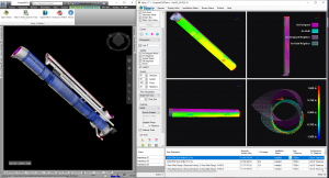
Verity (left) running alongside Navisworks, showing a heatmap comparison of the scan and the design model.
Embracing the Odd
I need to editorialize here a bit. When I saw the first press releases and showed a photo of the GTL-1000 to fellow surveyors, their reactions were, “That is funny looking.” I don’t care how odd it looks; this represents a bold solution that appears to solve a persistent BIM conundrum. Remember that some of the first integrations of lasers in surveying instruments were EDMs that piggybacked on the top of theodolites.
I know we have all seen instruments over the years that seem to have been exercises in “solutions looking for problems.” My take on this one is that a very big problem faced BIM implementation, and solving that precipitated the development of this software workflow and this instrument.
We might think it odd, but the folks who do not see it as odd at all but instead seemed excited about what the combined solution can do were the many attendees of the BILT event I mentioned above. They are the folks implementing digitalized construction—the GCs and BIM managers—clients who will be demanding more of such digitalized workflows from surveyors and geomatics practitioners. We need to learn to roll with such developments.
An ad campaign for the Volkswagen Beetle many years ago went, “It’s ugly, but it gets you there.” I do not view this solution as ugly; it’s more like a simple idea that has found utility in enabling increased efficiency. It not only can “get you there,” but maybe it can also get you to places you haven’t yet been to.