The second installment of a three-part look at the inner workings of high-precision surveying rovers.
In Part One of this series (xyHt magazine, September 2023 issue) we focused on the antenna, amplification, and housing elements of rovers. This installment continues with channels, boards, and gates.
Channels
There is a lot of misunderstanding about what receiver “channels” are and how they are counted. A modern rover can track 40 to 50 GNSS satellites, as well as SBAS sats, and communications satellites like those broadcasting PPP services via L-band.
And across the GNSS satellites there are 21-plus signals; two, three, four, or more each. For example, GPS L1, L2, and L5. And Galileo E1, E5a, E5b, E6, etc., and there can be variants of each. Counting how many channels you should have for three-signal processing should seem as simple as say, 40 x 3, or 120 channels. However, it is not quite that simple.
“Channels has no industry standard definition,” said Dr. Stuart Riley, vice president of technology/GNSS at Trimble. “The way Trimble defines a channel is that it is a piece of hardware. It’s digital hardware with some software on top of it, that is capable of tracking one signal from one satellite and creating a set of measurements: pseudo range, phase, etc.”
For example, if you wanted to track from a single satellite, GPS L1C, L2C, and L5, those three signals, you would dedicate three channels to it. Then, if you want to do that, for two satellites, there’ll be six channels, and so on.
“There are some locations presently in Asia where you can get 70-plus satellites,” said Riley. “So, we took a look at an upper bound of say 100 satellites, with five or six signals per satellite, and so that’s how we got to the large channel counts.
“Some within the industry, I don’t know how they define a channel, I don’t think there’s necessarily a common definition, because I do see some receivers with 1,000 channels or 2,000 channels,” said Riley. “And it’s not clear what they would do with that once you’ve tracked the signal with a single channel. Within a Trimble channel, we not only have the hardware to track the satellite, we also have additional hardware (correlators) for multipath mitigation, so using our definition of a channel, what are you going to do with those other channels? For example, to track Galileo AltBOC, that’s just one channel for us. Maybe some of these other receivers need to parallelize multiple channels to be able to track AltBOC, or for multipath mitigation, which is included in our regular channel, I don’t know.”
The subject of channels can get a bit fuzzy for end users. How many channels do we need? How many of say 1,500 or more channels stated on datasheets are actually used? Sheer numbers can be misleading. I remember a period about a decade ago when there was a lot of one-upmanship over who had the most channels touted in marketing materials.
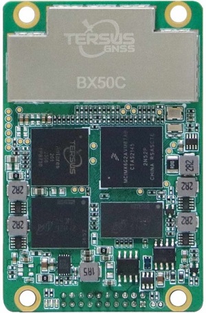
Example of GNSS boards for RTK Rovers: Tersus BX50C Source: Tersus
Ironically, some who touted the most channels were not yet using more than just GPS and Glonass (at the time). The number of channels is not a sole indicator of the capabilities of the rover. More important is to look at what signals are supported. For instance, a low-cost board in a drone or low-cost rover may state four or five constellations, however it may only be using two signals per constellation, missing out on the power of the other signal solutions.
Third-signal processing is powerful on many levels. For decades, GPS brought only one, then two signals: L1 and L2. Now, L5 has been added to newer satellites. Newer constellations started with three, four, five, or more signals. Besides being modernized and sometimes stronger, 3+ signals enable new approaches like AltBOC, and some carry messages for precise point positioning, such as the Galileo High Accuracy Service (HAS) in the E6 signal (bit.ly/3rMrgbG) and the B2B signal of Beidou. Modern rovers take advantage of 3+ signal processing.
“A third signal is better for a number of reasons,” said Neil Gerein, long-time GNSS engineer who is now vice president of marketing at Hexagon’s autonomy and positioning division. “Because the ionosphere is going to affect that third frequency different than just on the two frequencies, this provides you another measure of the local ionospheric error. And that’s an important thing in a rover because you’re within a certain distance from your base station. It’s important in terms of overall resiliency.”
“And third signal can be good for dealing with interference,” added Gerein. “If you have an interferer on one of the frequencies, then you can rely on the other ones, giving higher availability. And once you get down into the carrier phase tracking and resolving the ambiguities, it provides a fast way to do that, because you take combinations of the different frequencies to get what we call narrow lanes.”
Channels are a hardware/software feature of application-specific integrated circuits (ASIC), which is an essential part of the GNSS “board” (more on this later). Typically, this means one channel per each signal from each satellite. There can be approaches that seek to track each signal multiple times on separate channels, however, as Riley points out, they have more than enough correlators already to be able to track each individually, along with deploying multipath mitigation. There can be approaches to, for instance, for multipath mitigation that can take advantage of multiplexed signals, but this can be done without tracking a signal multiple times on separate channels.
There are other things going on in the processors of a typical rover. For instance, algorithmic approaches to mitigating or rejecting multi-path.
“In addition to multipath rejection in the physical elements of the rover design, there is lot that can be done in the channel tracking and signal matching steps,” said Gerein. “Since we’ve moved into high-speed signal processing, we can remove code phase and code-carrier phase multipath.”
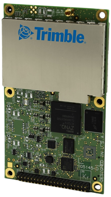
Example of GNSS boards for RTK Rovers: Trimble BD900 Source: Trimble
The new modernized signals have opened a lot of options for doing this. In particular, the Galileo AltBOC, a complex signal composed of four codes multiplexed to have constant envelope signal (bit.ly/3Os838p).
“One characteristic of AltBOC is a sharp correlation peak,” said Gerein.
AltBOC, as implemented for Galileo, is essentially two signals processed together making it a wide bandwidth signal that makes for a very steep correlation peak. “That is what you are tracking in the high-speed signal processing and can help detect and reject multipath,” he said.
Boards
The “board” is the heart of the GNSS system, and in some ways, it is the “currency” of the GNSS industry. A board typically is comprised of an ASIC, or in limited instances, Field Programmable Gate Arrays (FPGAs). More and more, boards are including IMUs and micro electromechanical (MEMS) components to measure acceleration and tilt. Boards are designed by GNSS manufacturers for their own rovers or sold as original equipment manufacturer (OEM) components to other manufacturers for integration into their own rovers.
For a period, years ago, nearly every rover manufactured around the world had OEM components from a handful of sources. Presently, many of the former OEM customers have begun developing their own boards.
The actual ASIC component of a board is relatively small. “These days, a digital ASIC is physically about 10 millimeters-by-10 millimeters with a much smaller internal die,” said Riley. “Yet it’s got millions of gates inside. Because of Moore’s Law about shrinking and doubling the number of transistors, you get into a new paradigm every few years. Size is not much of an issue, though the cost is pretty high because it’s a custom part and it’s very expensive to develop a custom ASIC.”
There are some inexpensive boards out there that rovers and drones and build-your-own folks tend to use, so be aware of the limitations (as discussed previously).
“The advantages of an ASIC for GNSS include lower power consumption, smaller size, and cheaper for high-volume manufacture,” said Ce Huang, research and development director at Tersus GNSS. “The disadvantages: it’s expensive and time-consuming to design and create the photomask (for mass manufacture) and the design/functions of the ASIC are fixed once put to manufacture. For FPGA, the biggest advantage is you can build a system with it (relatively) quickly, without very high cost, and you can modify the design/functions on the fly.”
In common practice in the industry, FPGA are used mainly for R&D, to work everything out before committing to the design of an ASIC.
There are software defined receivers (akin to software defined radios, or SDR) that put some or all of the functions that would otherwise be handled in an ASIC into standard processors. For instance, the Trimble DA2 antenna (bit.ly/DA2) for their Catalyst system is a low-cost, powered antenna that you connect via Bluetooth to a phone or tablet. There are processors in the antenna to run the SDR. In this example, a pay-as-you-go plan activates the SDR and positioning services.
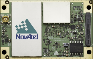
Example of GNSS boards for RTK Rovers: NovAtel OEM770 Source: NovAtel
An SDR might also be used in conjunction with an ASIC, for instance, to enable reception of L-Band broadcasts of PPP data, instead of adding in a separate physical receiver for that. While SDR are evolving, it is generally accepted that they do not yet provide the same robustness and capabilities of the dedicated and purpose designed gates of an ASIC.
“It’s a continuum, there is not one size fits all. It all depends on your product and what you’re trying to do,” said Trimble’s Riley. “On one level, you could have a software defined radio, and that’s defined as you have RF followed by an ADC to create digital signal. That runs into processors, a CPU, a GPU, or maybe a combination, with software.
“On the other hand, you’ve got an ASIC, which is custom gates that you develop. And once you’ve developed, it’s a locked design. And then somewhere in between, you’ve got an FPGA, which is this array of gates that you can, through software, reprogram. And they all have the pros and cons.”
Riley explained that if you take a software defined radio, in terms of power and cost, it’s a lot more expensive than an ASIC, as those can be mass manufactured with a per-piece price that is relatively low.
There are other pros and cons. “For example, in our first-generation DA1 for Catalyst, we leveraged spare CPU cycles in Android phones, and ran the SDR there,” he said. “However, dealing with so many variations among smart phone processors, putting some processor chips in the second generation, DA2 was a good move.”
An FPGA is somewhere in between. Flexible to configure, yet there is a cost associated with that. To have the same number of gates as an ASIC can be quite expensive. If you are not selling in huge volumes, like for specialized applications, it may pencil out. However, presently, for mass-manufactured systems for rovers, an ASIC is in many ways the best option.
Gates
These are the logic operations, that can run into the millions. Numbers of gates is an older metric, as the current gauge of logic operations may be expressed in terms of the area of the silicon chips. The fundamentals are the same as with older ASIC, however, designers are tapping so much more, by orders of magnitude.
Riley contrasts how things were done years ago: “It was done through schematic capture. Somebody actually went through and designed the whole logic using a schematic capture approach. There, you’re defining all gates, flip flops, XOR, etc. And you’re actually going through the CAD package and defining this; that’s fine if you don’t have that much logic, but it’s really not scalable to the systems now where we have millions of gates on the device.”
Today, they use a high-level programming language; essentially coding in a high-level hardware description language.
“Think of it as analogous to writing something in a programming language to put it to a compiler to take that to machine code,” said Riley. “It’s very similar, you’re writing a high-level description language; VHDL or Verilog are the two common ones. And then you use a compiler to translate that into gates.
“There are many extra steps for ASICs, such as meeting timing and physical layout. That’s a good analogy to the development phase where the functionality is defined.”
Part Three will appear in xyHt’s November 2023 issue. Gavin Schrock is a professional land surveyor who writes on surveying, mapping, GIS, data management, reality capture, satellite navigation, and emerging technologies.