The venerable GNSS rover, has evolved into an essential part of a surveyor’s toolkit, although some mystery remains as to what that magic box does and how it does it. To demystify this, we engaged GNSS engineers to help craft this three-part “explainer” series.
Part one
The work of a surveyor requires a lot of independent verification and being able to show how they arrived at a conclusion. It takes a lot of faith in a tool like a GNSS rover, the inner workings of which remain a bit of a mystery. However, through decades of use, development of best practices, and a growing understanding among surveyors of the science of GNSS, many surveyors have accepted rovers into their workflows.
There have been a lot of different design ideas over the past two decades, a lot of different approaches (and some gimmicks). After all, we don’t see things like gull wing doors on many cars, despite them being “cool” features of the DeLorean and some Mercedes. Presently, the culmination of a lot of parallel development has resulted in a kind of dominant design, in form factor and inner workings. Function has made modern GNSS rover heads look a lot alike, inside and out, and perform a lot alike.
But how does that thing really work? There are many types of GNSS receivers/antennas for a wide range of applications, however, this article is focused on GNSS rovers for surveying, construction, and asset mapping.
From the Top
If we start where the path of the satellite signals begins in the rover, the antenna is the most recognizable element of the design. It would take a whole separate story to examine all aspects and variations of the types of antennas built in or connected externally to rovers. However, there are some common fundamentals.
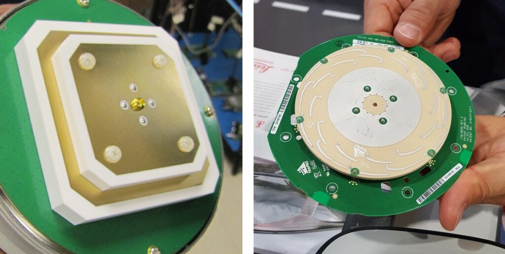
There are many different approaches to antennas designed for rovers, including a typical stacked-patch (left) – Image credits: G. Schrock
Typically, surveying and construction rovers employ patch style antennas. The patch can be a small ceramic square in the middle of a ground plane. There are lots of variations: pinwheel style, some with rows of “teeth” around the edge, and non-patch alternatives, such as helical antennas. The various designs seek to optimize reception, exclude outliers and multipath, and, where applicable, continue to work well when tilted.
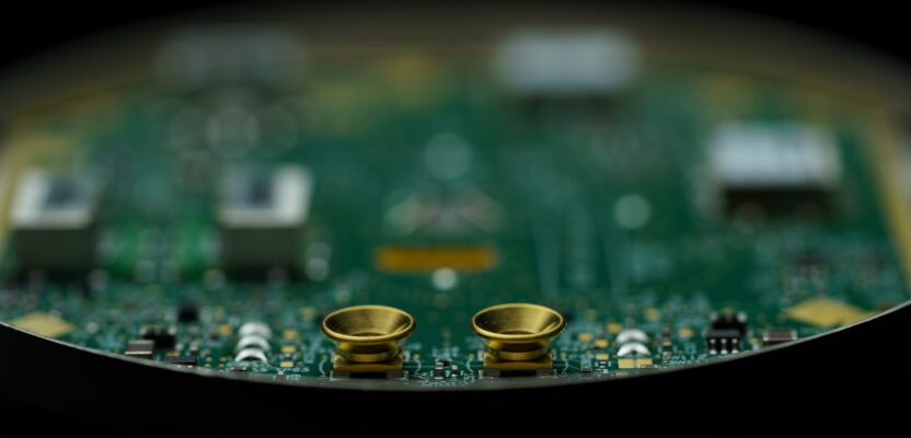
With patch antennas, there may be one or more contacts, or “pins,” that feed into the receiver. In the past you may have used a legacy L1-only rover that might have had only one contact. The bandwidth of a single contact is very narrow, adding a second increases bandwidth, can be designed for multi-axis, and opens up more options.
To receive the many bands of signals that four or more constellations broadcast, the rover antenna design will typically include multiple, stacked patches. “It is less about the constellations and is more about frequencies,” said Dr. Stuart Riley, vice president of Technology/GNSS at Trimble. Riley has been in GNSS design and engineering for 28 years and now leads the teams responsible for various elements of GNSS products for surveying, construction, agriculture, and more. For instance, his team designed all elements of the R12 and R12i rovers.
“The antenna does not care whether the signal is GLONASS, GPS, Beidou, Galileo, etc. What is important is to understand and design for the frequency/bandwidth of these signals,” said Riley. “Think about L1, MSS (like RTX), and several Beidou signals. Those are roughly in a similar band, then there is a bit of a gap, then L5, E6, and more signals clustered together. So typically, we have a couple of patches.”
Much of the antenna is passive. However, if you are also including the low-noise amplifier (LNA), the antenna assembly (element + LNA) does draw power. A tiny amount of power is supplied to the antenna from the receiver to power those active components (more on that later).
You may remember large ground planes in the past. They seem to have shrunk, along with the rovers they are paired with or built into. Just how small could a ground plane be and still be effective?
“Usually, the antenna ground plane diameter should be no less than about half of the target radio frequency (RF) wavelength,” said Ce Huang, research and development director at Tersus GNSS. “For a GNSS antenna, the RF signal wavelength is 0.19m for L1 and about 0.25m for L5. So, I figure the lower limit value is around 0.1m.” And indeed, we now see a lot of the new wave of small rovers that are about 10cm, or four inches in diameter.
“Much of the physical size of a rover is dictated by the antenna element,” Neil Gerein, long time GNSS engineer who is now vice president of marketing at Hexagon’s Autonomy & Positioning division. “You need to have a couple of things in the antenna: very good phase center offset (PCO) and phase center variation (PCV). And that’s the electrical characteristics on the antenna so that the electrical phase center is very stable for the precise measurements that the rover needs. And the other thing is the overall size of it, you want to get as much electromagnetic energy from the signal. That helps dictate the size, and it also dictates the amount of multipath rejection you have from the satellites.”
There is a lot of hardware and software magic going on inside a typical GNSS survey rover.
Gerein explained that a key factor in multipath rejection is that the signals have a right-hand circular polarization. If signals bounce off of a building or something nearby, the signal could arrive with a left-hand circular polarization.
“You want to reject those and low-elevation multipath. Good rejection of left-hand circular polarized signals, good PCO and PCV, as well as being able to receive the signals on all frequencies,” he says.
But how can an antenna continue to perform well when tilted? In designing rovers for no-calibration tilt compensation, in some instances, there have been design changes made to antennas. For instance, Leica’s GS18 T, the first of the no-calibration tilt compensated rovers released five years ago, incorporated a new antenna variation to continue to track many satellites when tilted.
“There are two things we have put to special consideration when designing a rover antenna for tilt compensation,” said Huang. “The L1/L2 phase center distance. When doing tilt measurement, the traditional methods of compensation of the L1/L2 phase center offset (PCO) vertically (for RTK solutions) are not suitable anymore. One solution is trying to design the rover antenna with L1/L2 phase centers very close to each other (about 1~2mm). Then you don’t need to know the tilt angle very precisely to compensation the L1/L2 PCO.”
The other, Huang said, is elevation mask. “Usually, a GNSS antenna has elevation mask at 0 to 10 degrees. That makes sense when the antenna is vertical. In tilt measurement, we expand the elevation mask to -10 to -20 degrees, so the antenna can still receive signals from all directions when it’s tilted up to 30 degrees.”
Housing
Round, square, small, or large? “Burger-on-a-pole,” “chicken bucket,” “lunchbox,” “discus,” “carrot,” “bullet.” The various form factors of rovers get described in many ways. Sometimes, integrated receiver/antennas are called “smart antennas.” Why are particular form factors chosen?
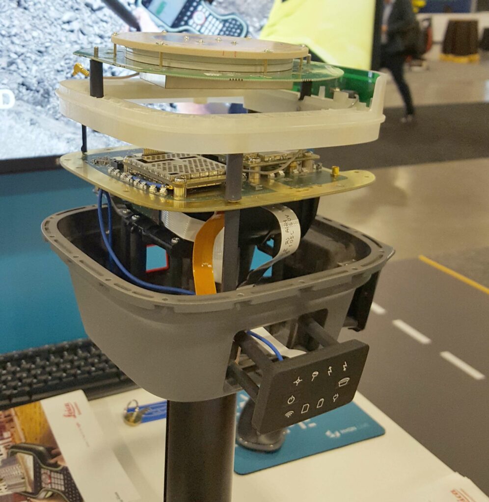
GNSS developers have told me that it is mainly due to what they are putting inside. Namely, how to make room for the various boards, battery compartments, IMUs, cameras, radios, WiFi and Bluetooth modules, and, if applicable, extra slots to enable battery hot-swaps. More features often mean a larger rover, however, there are continual improvements in miniaturization. A rover’s small size may not mean it will necessarily be less capable. The form factor and housing are also designed to reduce the impacts of shock and environmental factors.
“What we do at the receiver card area is we build it to be able to handle that shock and vibration,” said Gerein. “Of high importance is the reference oscillators. If you start vibrating those, that affects the entire solution. In our case, it’s on our receiver card: the temperature compensated crystal oscillator (TCXO), and in all our OEM receivers, they’re all set up for high vibration and shock. For a rover on a pole, as you move it point-to-point you hit that pole on the ground. That can create a vibration on the oscillator. And if you don’t account for that, it will work its way straight into the carrier phase measurements.”
Most high-end rovers have sturdy alloy housings. These are important to protect what’s inside and are designed to withstand drops from standard pole heights. There can be many seals to achieve IPV66, 67, and 68 ratings for dust and moisture.
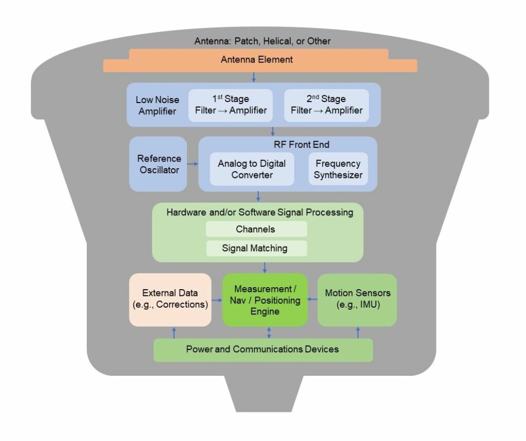
Block diagram of a typical GNSS survey rover. While there are various approaches to rover design, there are some common and essential elements. Of course, this is not to scale. – Graphics: G. Schrock
As one designer said, the solid housing was actually challenging to create to meet design goals, and to also be cost effective. Square-ish designs, some say, can more easily accommodate faceplate style user interfaces, though these are sometimes added to round housings. Some say that round designs and rovers with helical antennas do not snag as much when carrying them thorough dense vegetation (though I find any shape seems to).
We are beginning to see more rovers with helical antennas. While there are numerous papers contrasting the performance of helical vs. flat, there appears to be much nuance in considering the advantages or disadvantages of each.
There could be specific applications in mind when choosing one or the other. For instance, one of the considerations Bad Elf said it had in choosing a helical antenna for their Flex rover was to make a sleek form factor, that GIS and asset mapping users could more easily push up through vegetation.
We do not suggest that you purposely do a drop test of your rover. But rest assured that the manufacturers have. Even most plastic-housed rovers can withstand the impact of a pole blowing over, and the head hitting the ground. One manufacturer showed me a video of one of their alloy-housed rovers being smacked against a brick wall, yet it still continued to operate.
Amplification
A GNSS satellite 20,000 km distant, with a limited power budget, is broadcasting signals that are quite weak by the time it hits a rover. Amplification is employed to enable the signal to stay strong and consistent through the many paths it needs to take within the rover.
Low-noise amplifiers (LNA) are an active component within external and integrated rover antennas. There are multiple signals coming in, within various frequency bands, so there may be multiple LNAs.
“You amplify the frequencies individually. For example, in the antenna/LNA you cannot separate GPS L1 from Galileo E1, the signals are on top of each other. Instead, you amplify the L1/E1 band,” said Trimble’s Riley. “You amplify before sending them through a single antenna cable if you’ve got a separated antenna and receiver.
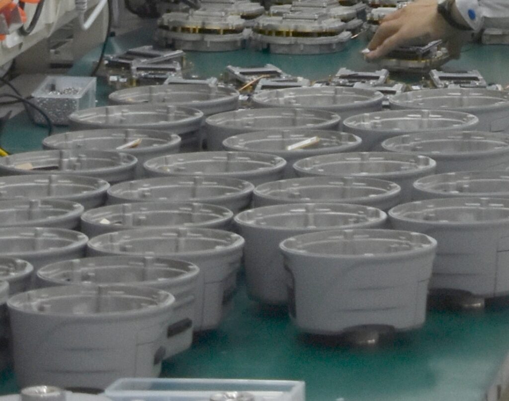
Rover housings being prepared for assembly at a GNSS factory – Image credit: G. Schrock
“In the case of a smart antenna, we typically don’t combine and so we’ll have multiple feeds coming down to the GNSS board. The LNA is critical for two things: First of all, you could lose the signal in the noise, so if you don’t amplify before you start losing, you’ve lost it for good.”
His example was where you might have a 1-, 2-, or 3-dB loss from the combined elements of the antenna, you would lose that for good and there’s nothing you could do about it. Therefore, by having some gain upfront you prevent that effect.
“And secondly, it’s critical for robustness,” added Riley. “Making sure that that amplifier is not going to be saturated by out-of-bounds signals, such as Ligado and other signals is critical.”
The LNA are physical devices, and there may also be physical filters. There are many types, such as ceramic, cascade, and even large-cavity filters (though the latter may not be common for rovers). The most common application for filters is to simply minimize out-of-band signals, to ensure that only desired signals are then amplified.
It can be a delicate balance. It is possible to over-design and filter too narrowly. For military-grade antennas designed for use in areas of jamming and spoofing, the design approaches and use of filters is far more complex than in a standard commercial rover.
“Detection and mitigation of interference can be done in many places, starting with the antenna, the amplifier, and first stage filters,” said Gerein. “To keep and receive just the signals you need to process in the bands of interest for GNSS, you can design the antenna for this and add hardware filters that keep out strong adjacent band interference. And as you transition into the next stage of high-speed signal processing, you can add a stage of digital filtering, which you might not have had 20 years ago. You can filter out at the start, then cascading down as you get into the digital realm, with digital filtering to tighten that up and help keep out those interferers.”
Gerein has helped engineer and design receivers and antennas specially for interference detection and rejection for the defense sector.
As the signals from the satellites are analog, the next step in getting the signals to the receiver is the analog to digital converter (ADC). Following that step, things can get quite a bit more complex. ν
Continued in Part Two, xyHt October 2023 issue
Part Three, xyHt November 2023 issue