Here’s a selection of CAD applications and features that I find a lot of people aren’t aware of but can save picks and clicks, time and money.
DWG Convert in DWG True View
 DWG TrueView is a very, very stripped-down version of AutoCAD that allows you basically to open and plot DWG and DXF files. You can’t edit or even save files, but you are able to change layers and take a few measurements.The best part? It’s FREE! Autodesk releases a new version of TrueView every year at about the same time they release AutoCAD. You can download DWG TrueView from Autodesk’s website.
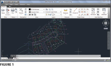
If you need for a few extra staff members to be able to open or plot drawings but you aren’t ready to purchase full copies of AutoCAD for part-time users, TrueView may be the ticket. For instance, it might be helpful to install TrueView on the computers of admin or field staff. Project managers or principals who aren’t necessarily CAD experts may also want to install it for when they need to open, review, and plot drawings.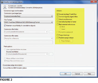 The most valuable feature within TrueView is the DWG Convert command. DWG Convert can be used to convert files from any version DWG to any version (Figures 1 & 2). DWG TrueView 2014 supports DWG files from R14 to 2014. You can convert one file or many at one time. Additionally, you can also configure the setup so that clean-up routines such as Purge, Audit, XREF-binding, etc. are also run during the conversion process.
Convert Text to MText and Vice Versa
Here’s a little “Did you know…?” tip: Did you know that you can use the Explode command to convert MText entities into Text entities? And, did you know you can use the TXT2MTXT command to convert one or more Text entities into one MText entity?
Editing Your PGP File
If your first response to this header is, “I didn’t even know I had one!” you’ll probably like this tip. Have you ever wondered how AutoCAD knows that “L” is a shortcut for the LINE command, “E” is a shortcut for ERASE, “Z” is for ZOOM, and so on?
AutoCAD calls these shortcuts “Command Aliases,” and they’re defined in a Program Parameters’ file called acad.pgp. It seems very non-techy, but the PGP file is a text file that you can edit to make the aliases work best for you. Sometimes, the hardest part of editing the PGP file is finding it! The file loca-tion will vary slightly based on your operating system, user name, and version of AutoCAD but, if you can find your user \Support folder, you should find the PGP file. For instance, here is the path on my Windows 7 computer: C:\Users\Jennifer\AppData\Roaming\Autodesk\C3D 2013\enu\Support.
If you’re using the ribbon in newer versions of AutoCAD-based programs, you can Edit Aliases from the Customization panel on the Manage tab (Figure 3). If you’re using pull-down menus, look for the Edit Program Parameters command under Tools > Customize. You can see the pared-down version of my acad.pgp file in Figure 4. To make changes, you only need to follow the formatting already established. For instance, if you’d prefer to have the alias “C” execute the CIRCLE command instead of COPY as I have it, you’d only need to replace *COPY with *CIRCLE, then Save and Exit the file.
If you make changes, you should first make a copy of the original file and then save a copy of your customized version in a separate folder away from the Autodesk installation files.
See Figure 5 for a sample of aliases for the most frequently used AutoCAD commands.
It’s also important to understand that the PGP file is loaded into AutoCAD only when you start the program. Any changes you make to the PGP file while the AutoCAD session is in progress will not take effect until you exit and then re-start the program. However, you can use another handy command called REINIT (for re-intialize) to reload the PGP file while you’re in an active session.
Stop Asking Me That!
You know how annoying it can get—you have a few lines drawn on your screen, their endpoints match up perfectly, and all you want to do is join them into a polyline. So, you start the PEDIT command and get the seemingly sarcastic reprimand and that question:
Object selected is not a polyline! Do you want to turn it into one? <Y>
Well, of course I do—why else would I have started the PEDIT command?!
Instead of wasting those picks and clicks, try changing your PEDITACCEPT variable from the default setting of 0 to 1. Then, if you select an entity that’s not a polyline, it will change it into one automatically.
VIEWRES Setting
Do you ever notice that your circles sometimes look more like stop signs, like in Figure 6? Usually this happens when you’re zooming in and out, and it can also affect arcs and polylines with arcs.
You can mostly keep this from happening by adjusting the VIEWRES settings. VIEWRES can be changed by typing VIEWRES at the command line and then changing the “circle zoom percent” to the highest possible setting: 20000. After making this change, the drawing screen is regenerated and you can see the immediate difference, like in Figure 7.
You can also change the setting from the Display tab of the Options dialog box, as seen in Figure 8.
One thing to pay close attention to in the Options dialog box is the presence of the “drawing” icon. ![]() This icon indicates that the setting is saved to the current drawing file (as opposed to the program installation). This means that each time you start a new drawing, this setting may have to be changed again. To set the VIEWRES Arc and circle smoothness to 20000 in all new drawings, open and make this change in each drawing template (.dwt) file you use to start new drawings.
This icon indicates that the setting is saved to the current drawing file (as opposed to the program installation). This means that each time you start a new drawing, this setting may have to be changed again. To set the VIEWRES Arc and circle smoothness to 20000 in all new drawings, open and make this change in each drawing template (.dwt) file you use to start new drawings.
I hope you enjoyed this article and found some helpful information. Feel free to follow up with me if needed.