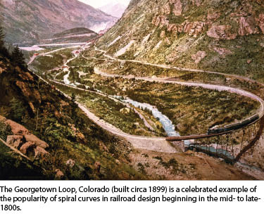
There are very practical reasons for employing spiral curves: chiefly to effect a safe transition from tangent to curve for rail cars and vehicles, particularly at high speeds. Whereas a driver of a car can adjust his or her steering to safely negotiate the sometimes-abrupt transition from a standard tangent-to-circular curve, a train has no such option. The spiral curve became the standard for rail and a substantial number of the world’s highways. Evidence of the popularity of spiral curves for safety and aesthetic purposes can be seen in the post-war boom in suburban developments and scenic parkways.
Centerlines of spiral curves, while sometimes mildly challenging to understand, are relatively easy to stake out for construction or retrace. But the offsets are another story; respective offsets for right-of-way are completely unrelated spirals of their own definition. There are many ways to stake offsets to spirals: perpendiculars from short “chords” even “exploding” of spirals in CAD and offsetting the “debris” (as some call it).
Presented here are the fruits of many decades of experience and dedication in seeking a mathematical solution to directly relate the centerline spiral definition to that of its offsets. In this personal narrative the author shares his journey to a solution of his own design, complete with examples and formulas you can try for yourself.
I started my surveying career in 1977 after graduating from Albuquerque Vocational Institute in New Mexico with a diploma in construction drafting, which included architectural design and surveying technology. I was hired straight out of school by Western Engineers in Casper, Wyoming. I was put in charge of several survey crews that provided construction staking for a 35-mile-long railroad spur line from Bill, Wyoming to Douglas, Wyoming.
The railroad alignment contained spiral curves, which is the standard for railroad centerline curves. This was my first introduction to spiral curves. I bought a book titled Railroad Curves and Earthwork by C. Frank Allen, SB that gave me the background information and formulas I needed to layout the spiral curves using a 10-chord method.
Staking the centerline was not a major challenge. The challenge came in staking the right-of-way line 100 feet left and right parallel to the spiral curve for the fencing crew. The method described in the book was to:
- stake the centerline, then
- occupy the points along the centerline spiral curve,
- turn the appropriate angle to get perpendicular to the centerline, and
- measure out the offset distance left and right to the right of way line.
This method was slow and time-consuming. Where there was a significant vertical difference from the centerline to the right-of-way line, the slope distances were required.
Back then, there were no methods or formulas for staking the spiral offset curve along the right-of-way line. In 1977 the survey equipment consisted of theodolites, steel chains, and a large (big orange box) electronic distance measurement device (EDM) that was awkward to use. The company I worked for only had one EDM. It was used for the initial vertical and horizontal control but was not available for the construction staking we were doing. The only equipment available to me was a Wild T2 and T16 theodolite, a 100-foot and a 300-foot steel chain. Using today’s survey equipment (GPS/total station) would have made the work so much easier.
Because I like math, I spent many hours at night in the hotel room calculating by hand coordinates for the spiral offset points that could be staked radially from a nearby control point (personal computers had not been invented yet). I did this while the crew spent their time at the local bar. The longest distance that could be measured was 300 feet from a control point. Therefore, many intermediate control points were established between the major control point network that was established earlier with the EDM and theodolite.
 I became friends with the professional engineer on the project for Burlington Northern, and together we spent many hours trying to come up with a process of calculating and staking the offset spiral curve using the same method that was used for the centerline. We both struggled to come up with the formulas with no success.
About 15 years ago, I became a consultant with the Arizona Department of Transportation (ADOT) Right of Way Plans Section. I have worked on many right-of-way projects, some of which contained highway spiral centerline curves. In some cases, the right-of-way (R/W) line for these centerline alignments paralleled the centerline spiral curve. This was the same scenario as the railroad right of way line that I had worked on many years earlier. The major difference is that now, with the invention of GPS, staking the R/W line has become much easier.
The challenge still remained that there were no formulas for calculating the offset curve or methods for describing the spiral offset curve in a legal description where a property is contiguous to the right-of-way line except for making reference to the centerline spiral. There are many coordinate geometry computer programs available that only approximate an offset spiral curve that is, more or less, parallel to the centerline spiral. I consulted with other ADOT right-of-way consultants and the technical leader/project manager of the ADOT Right of Way Plans Section to come up with a solution to best work with spiral offset curves.
After 33 years of working on a solution, I have finally derived a method that will calculate a spiral offset curve that is parallel to the centerline spiral. To demonstrate it, I have developed a series of seven exhibit sheets with formulas, definitions, diagrams and examples.
The Full Transition Spiral Curve is a compilation of the many existing formulas for centerline spiral curves. They are formatted in a simple, easy-to-follow manner for calculating a full transitional spiral curve for a highway and/or railroad curve. Most survey publications (books) do a thorough job of describing the theory behind spiral curves and how they came to be in use. My goal was to create a step-by-step method for calculating centerline and offset spiral curves.
The Spiral Offset Curve is the method for calculating spiral offset curves using the offset distance from the centerline. The standard clothoid formulas for the centerline spiral curve will not work for an offset curve. Therefore a set of formulas was needed that would allow for the derivation of the rate of change, length, deflection, chord, X, Y, U, and V values. These values can then be used in descriptions when creating a legal description along an offset spiral curve using familiar terms for spiral curves along centerlines.
Points on Spiral Offset Curve contains two methods of calculating points along the spiral offset curve. The first method is calculating a point by the traditional method along the spiral centerline, then perpendicular left or right to the right-of-way line. The second method is to calculate the point along the spiral offset curve using the right-of-way incoming tangent line.
Area of Spiral Chord is for calculating the chord area for the centerline and spiral offset curves. This area can then be added or subtracted from the parcel adjacent to the right-of-way line to get the true area for the parcel. The formulas are given to calculate the area manually, if desired, but it will take some time to do so. The best method is to use a computer program to run the iteration.
Spiral Curve – Line Intersection is for calculating the intersection of a line with the centerline spiral and offset curve. The formulas are given to calculate the area manually, if desired, but it will take some time to do so. The best method is to use a computer program to run the iteration.
Full Transition Unequal Spiral Curve is for calculating a full transition curve with unequal spiral curves on each end.
Spiral Curve – Station – Offset is for calculating station and offsets to the centerline spiral along the tangent line (P.O.S.T.) and on the spiral curve itself (P.O.S.). The formulas are given to calculate the station/offset manually if desired, but it will take some time to do so. The best method is to use a computer program to run the iteration.
I have also developed training material for calculating a centerline spiral curve and a spiral curve computer program to calculate the SC series exhibits. The above exhibits, training material, and computer program are available for download from my website at www.cc4w.net. You are free to download and use this material. All that I ask is that the material remains in whole and that the copyright information is not removed.
References
Railroad Curves and Earthwork. C. Frank Allen, SB.
Route Surveying and Design. Carl F. Meyer & David W. Gibson.
Surveying Theory and Practice. Davis, Foote & Kelly.
Acknowledgements
A special thanks to the following individuals for their valuable input and insight in working with spiral curves.
ADOT Right of Way Plans Section Technical Leader/Project Manager Dan Miller RLS
AZTEC Engineering, Alan Reece, RLS RBF Consulting, Chad Woolgar, RLS GMTS
Right of Way, David Shane, RLS