Swift Navigation’s Piksi® Multi is a multi-band, multi-constellation GNSS receiver that supports GPS L1/L2, GLONASS G1/G2, BeiDou B1/B2 and Galileo E1/E5b for RTK measurements and positioning and SBAS for robust sub-meter positioning in non-RTK mode. Critical to the accuracy of—and continuous improvements to—Swift’s receivers is ongoing testing in varying dynamic environments and conditions. This testing ensures that Swift products deliver as expected to customers around the globe, no matter the application.
This dataset explores one such dynamic data collection test from a manned aircraft and demonstrates the data collection process along with the post-processed results achieved using third-party post-processing tools.
Product Tested
Piksi Multi is Swift Navigation’s flagship product. In addition to it being an affordable and centimeter-accurate receiver, the 26-gram, PCBA (Printed Circuit Board Assembly) module is ideal for integration by OEMs. Despite these attributes, Piksi Multi has exposed connections and is not always ideal for field test environments.
For this test, the Swift Navigation Duro® receiver was used. Duro is a ruggedized version of Piksi Multi. Built for outdoor industrial applications, Duro is an IP67-rated, easy-to-deploy sensor that is protected against weather, moisture, vibration, dust and water immersion up to 1 meter. Its features combined with the robustness of the power, IO and antenna connections made Duro the ideal receiver for a dynamic flight test.
Highly Dynamic Test Environment
Swift customers operate in an array of environments and applications—including unmanned aircraft systems (UAS), autonomous vehicles, snow and earth moving equipment, agricultural and grounds keeping vehicles and robotic systems. This particular test was carried out in a manned aircraft with relatively higher acceleration, velocity and directional changes than traditional customer applications.
Manned aircraft flights encounter GNSS technical challenges due to aircraft banking, pitching, and direction change—for example turning on to photogrammetry flight lines. Acceleration and rotor disk interference with GNSS signals can occur to a lesser degree depending on aircraft type and acceleration.
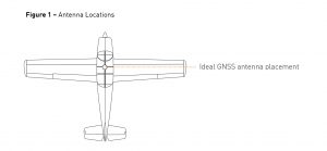
A fixed-wing aircraft was used in this test and a compromise was made when it came to the placement of the GNSS antenna. Ideally an FAA-certified, multi-band GNSS antenna would be installed on a flat surface of the upper fuselage (see Figure 1). Due to time and equipment constraints, an ideal antenna installation was not possible. For this test, a multi-purpose antenna was placed inside the aircraft above the instrument panel.
Test Profile
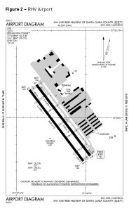
The test was conducted in Northern California with the departure point at Santa Clara County’s Reid Hillview (RHV) airport (see Figure 2).
Upon departure, a right 180º turn was executed as the aircraft climbed to the test altitude of 3,000 feet mean sea level (MSL) (see Figure 3). Power to the Duro was reset inflight to observe receiver reacquisition performance after a power loss.
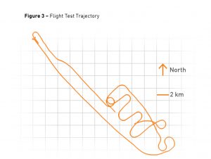
Once at the planned test altitude and area, several maneuvers were executed—including high bank angle (>40º) turns. The aircraft was then maneuvered to mimic typical aerial photogrammetry flight lines. Each flight line was 30 seconds in duration connected by high bank turns during level flight. These maneuvers were executed between GPSTOW 248900-249400 and can be observed in the plots below.
Thereafter, additional turns and steep descents were made enroute to the next planned altitude (2,000 feet MSL) at which point the test was concluded and the aircraft was flown back to its base at RHV.
Data Processing
This particular dataset was created utilizing Post Processed Kinematic (PPK) techniques which differ from Real Time Kinematic (RTK) solutions. While RTK delivers a quality solution for real-time applications such as automotive and machine control, in aerial mapping a PPK solution is often preferable as it offers more flexibility with the information processed post-flight and is not subject to correction signal dropouts typically found in RTK applications.
Similar to RTK, PPK combines base and rover measurements to solve carrier phase ambiguities and generate a position fix with high accuracy. However, unlike a real-time solution, PPK allows the user to process the data in a time-reversed direction. This ultimately yields a higher number of integer-fixed epochs in a typical dataset. In addition to increased availability, the two solutions can be compared to against each other, which gives the user increased confidence in the accuracy of their solution and alert them to potential problem areas in the data.
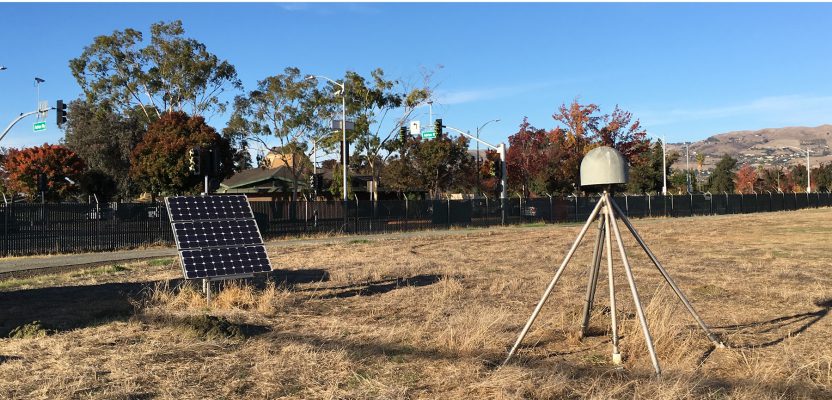
For this test, the base station for the GNSS receiver was a conveniently-located CORS station based at the departure airport, Station P226, which is part of the Plate Boundary Observatory Network (due in large part to continuous seismic monitoring throughout California, there are over 850 CORS stations in the state). The P226 station is located at 37.3368 degrees north latitude and 121.82559 east latitude and is equipped with a high-precision choke ring antenna (see Figure 4).

Test Results
During the flight test, dual-frequency GPS and GLONASS raw measurements were collected from the base and the rover. After collection, the data was processed using a well-known—and widely used—third-party processing software.
Key post-processed data attributes analyzed include: combined solution separation, estimated position accuracy, GNSS signal availability during maneuvers and signal/solution reacquisition after power interruption. Of these key attributes, solution separation was considered the most paramount as it best represents the accuracy and repeatability of the position solution.
Plotted data starts slightly before takeoff and ends just after landing and has been filtered by epochs with integer-fixed ambiguities in both processing directions. Solution accuracy and separation metrics were generated by converting the PPK solution geodetic coordinates to a North/East/Up reference frame.
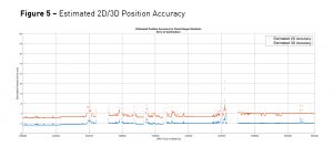
Figure 5 shows the estimated position accuracy of the dataset. The performance is impressive with estimated horizontal accuracy around 2 cm for most of the dataset and with spherical error estimated to be around 4 cm.
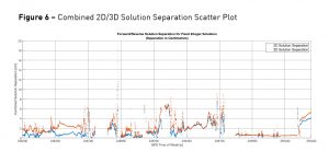
The verall distribution of Forward/Reverse 2D separation values is less than 4 cm for 95% of epochs. Even with dynamic flight conditions and sub-optimal antenna placement, fixed 2D separation never exceeds 12 cm and 3D separation remains below 20 cm.
The combined 2D/3D solution compares the forward and reverse processing of the data collected in flight and acts as a quality control tool by providing another measure of accuracy. In Figure 6 the Solution Separation Plot shows differences in position in the millimeter range.
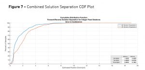
The Combined Solution Separation Cumulative Distribution Function (shown in Figure 7) also shows the differences in the forward and reverse processed solutions. No information is “shared” between the two processing runs; they are processed independently. The CDF plot in Figure 7 shows fixed integer solutions not exceeding the 6 centimeter level in horizontal accuracy.
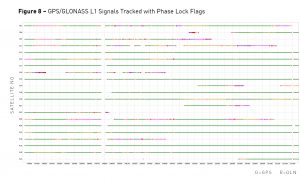
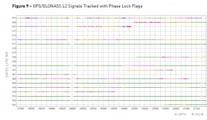
In both PPK and RTK, solution accuracy is highly dependent on the ability to fix integer ambiguities. The ability to fix ambiguities is largely dependent on not only the number of satellites used, but also the receiver’s ability to maintain constant phase lock with the satellites. Figures 8 and 9 plots and show the excellent performance of the Duro/Piksi Multi L1 and L2 measurement engine in the context of maintaining phase lock while maneuvering. Carrier cycle slips are flagged with red markers.
Conclusion
The intent of this test flight was to demonstrate the positioning accuracy and overall performance of Swift Navigation’s GNSS technology in a highly dynamic environment—in this case onboard a general aviation aircraft.
The results achieved were impressive and included solution separation and estimated position accuracy values in the sub five-centimeter range, excellent satellite tracking characteristics and rapid signal reacquisition after power to the Duro receiver was reset.
The poor antenna location degraded availability and accuracy during the flight test. Despite these limitations, the Duro demonstrated both the ability to deliver centimeter-level accurate results in a dynamic environment and to achieve fast reacquisition times. Future testing may see further improvements with newer versions of Swift firmware which now use four constellations—GPS, GLONASS, BeiDou and Galileo.
Visit www.swiftnav.com to learn more about Duro and Swift’s affordable, highly-accurate GNSS receivers.