 A frank discussion of the different heights used in surveying, what’s inside a geoid model, and how geoid model data is used within GNSS software to produce elevations.
Certainly most geospatial professionals who have used Global Navigation Satellite Systems (GNSS) within their surveying workflows have come across the term “geoid model” before. But who actually knows what data is contained within a geoid model? Further yet, who knows how this data is used in conjunction with a GNSS-derived position to produce point elevations within a specific vertical datum? I assume that not many readers have answers to these questions, and likely most have not even pondered these questions before.
Surveyors know that we should select and set the appropriate geoid model within our RTK collection software or static post-processing software in order to produce accurate elevations. But what is really happening within this process? How can we (the end user) be sure that the displayed elevation coordinates for our points of interest are accurate? This article examines the different heights used in surveying, what’s inside a geoid model, and the internal process of how geoid model data is used within GNSS software to produce elevations.
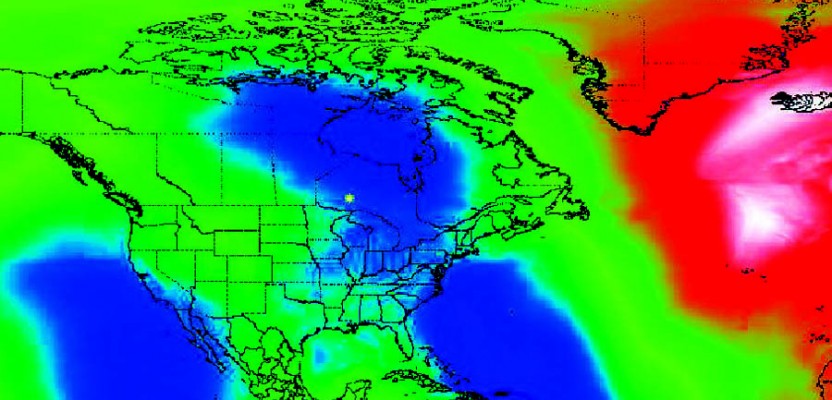
The topic of geoid models is currently in the spotlight up here in Canada, as the federal government recently released a brand-new vertical datum, the
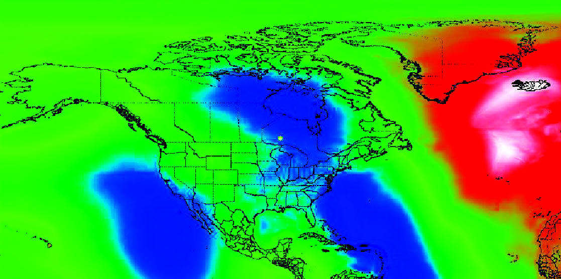
Figure 1
Canadian Geodetic Vertical Datum of 2013 (CGVD2013) (Figure 1). What makes this vertical datum so different (and scary for most) is the fact that it is realized (i.e., made tangible) solely via a geoid model (Canadian Gravimetric Geoid model of 2013, CGG2013).
In short, surveying professionals are no longer required to tie in to federal benchmarks in order to establish an accurate elevation within the CGVD2013 vertical datum. A surveyor can now use GNSS positioning techniques (provided the horizontal datum of the derived GNSS positions is carefully selected and realized) along with a single geoid model to establish accurate elevations anywhere in Canada.
Combining the new geoid-model-based vertical datum with the fact that Canada has not seen a new vertical datum in over 80 years naturally means that this new vertical datum will be adopted slowly and will be met with some degree of resistance by practitioners. However, this type of vertical datum will increasingly become commonplace throughout the world, and the surveying and geomatics community should not fear this change. The positives of this type of modernized vertical datum greatly overshadow most of the perceived negatives, and this is the future of elevation determination.
So, let us embrace the change and welcome the new geoid-model-based vertical datums as part of our daily workflows. Let us gain confidence in the ability to make our lives (and projects) simpler and more efficient by using geoid models and GNSS positioning to accurately determine elevations. (Note that even if your governing vertical datum is not solely realized by a geoid model but rather realized via physical tie-ins to demarcated benchmarks, the use of a geoid model in conjunction with GNSS positioning can still be very important when determining elevations.)
-
Types of Heights
Ever since elementary school we all learned that the height of something is measured with respect to mean sea level (MSL).
For example, we learned that Mount Everest is 29,035 feet above sea level. As we began studying surveying/geomatics later in our lives, we learned that there is a slightly different surface than MSL that we use to measure heights from, and we call this surface the geoid.
The complete definition of what the geoid is along with where it is specifically located involves the science of physical geodesy and a firm understanding of the gravity field of the Earth (see archived issues of Professional Surveyor magazine for the basics). We will simply recognize the fact that the geoid is the reference surface (i.e., where height = 0) for the type of heights we want, and it very closely approximates MSL. Specifically, we call heights that are measured from the geoid orthometric heights or, more commonly, elevations (symbolized as H) (Figure 2).
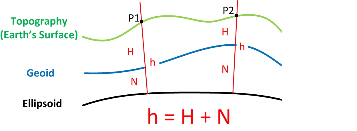
Figure 2
Some end users of GNSS equipment may be unaware that the intrinsic height coordinate determined using GNSS equipment is not an elevation but rather a height above or below a different reference surface, a surface we call a reference ellipsoid. Heights measured above or below a reference ellipsoid are known as ellipsoidal heights (symbolized as h). Traditionally, reference ellipsoids were used only as part of a horizontal datum’s definition and hence as a reference surface for horizontal positioning (i.e., latitude and longitude). Nowadays, reference ellipsoids are commonly used as a reference surface for both horizontal and vertical positioning, sometimes referred to as 3D datum.
Unfortunately, the waters become further muddied due to the fact that there are numerous horizontal datums (each utilizing a specific reference ellipsoid) used throughout different regions on the world. Hence, the term “ellipsoidal height” is ambiguous without specifying the horizontal datum being used. For example, the Global Positioning System (GPS) uses the World Geodetic System of 1984 (WGS84) as its horizontal datum. The ellipsoidal height that a GPS receiver determines will fundamentally be above or below the reference ellipsoid used in WGS84.
“But wait a minute,” you might be saying to yourself. “I know I’ve seen the term elevation displayed on my handheld GPS unit.” And you would certainly be correct. However, what is not so obvious is the fact that the manufacturer of your handheld GPS has a crude global geoid model loaded into the memory of your unit. This geoid model is used to automatically convert the GPS-derived WGS84 ellipsoidal height into an elevation (of low accuracy).
GNSS positioning methods naturally produce ellipsoidal heights, and these heights are best converted into elevations using data from a geoid model. Note that some of the experienced GNSS practitioners may use other methods for determining elevations using GNSS rather than using a geoid model; these methods can work well for small extent projects but quickly deteriorate as the extents of a project area increase.
The difference between the ellipsoidal height and the elevation for a single point on the Earth’s surface is known as the geoidal undulation, also known as the geoid height (symbolized as N). Using a best-fitting reference ellipsoid for the entire globe, the values for geoidal undulations range from approximately +/- 100 m throughout the world. The geoidal undulation is the Rosetta Stone for enabling GNSS positioning to determine accurate and precise elevations.
A geoidal undulation simply yet accurately relates elevations to ellipsoidal heights. If an accurate geoidal undulation is subtracted from an accurate ellipsoidal height, an accurate elevation will be the result. However, if either the geoidal undulation or ellipsoidal height is inaccurate then obviously the elevation will also be inaccurate.
Until only recently the ability to create an accurate wide-area geoid model was difficult. Thanks in large part to recent satellite missions, such as the Gravity field and steady-state Ocean Circulation Explorer (GOCE), new levels of precision in measuring the Earth’s gravity field have been achieved. This, in turn, has resulted in more precise and more accurate geoid models, such as CGG2013.
-
Geoid Model Data
A geoid model is nothing more than a regularly spaced collection of geoidal undulation values over a specific geographic region.
For example, the CGG2013 geoid model has a sample spacing of two arcminutes in latitude and longitude between successive sample points (Figure
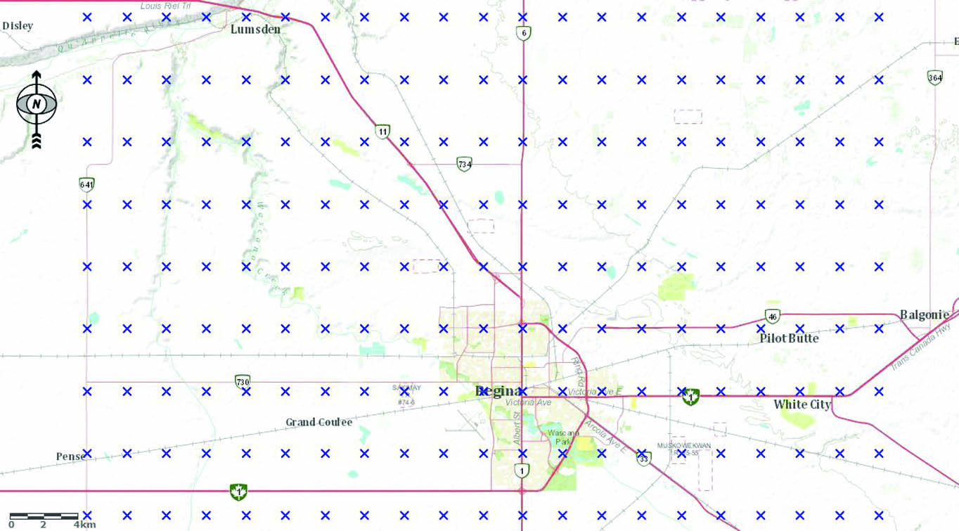
Figure 3
3). It is very important to understand that a geoid model only converts ellipsoidal heights measured with respect to a specific horizontal datum to elevations within a specific vertical datum. This means that the horizontal datum used in GNSS positioning must be accurately realized and also must match the designated horizontal datum of the geoid model in order to produce accurate elevations.
For example, the new CGG2013 geoid model used in Canada will convert NAD83 (CSRS) ellipsoidal heights into CGVD2013 elevations. If a user mistakenly uses WGS84 as the horizontal datum for his or her GNSS positioning along with the CGG2013 geoid model, the resulting elevations would not be realized within the CGVD2013 vertical datum. Hence, it cannot be stressed enough that the correct horizontal datum be realized when collecting GNSS positions where precise and accurate elevations are required. Thanks to advancements in Real-Time Networks (RTN) and Precise Point Positioning (PPP) techniques, the ability to quickly and accurately realize a specific horizontal datum using GNSS equipment is becoming commonplace within today’s industry.
-
Geoid Model Interpolation
How do we determine an accurate geoidal undulation for a point located in-between the geoid model sample points?
As we discussed, a geoid model contains only precise geoidal undulation values at regularly spaced sample points. The sample points are usually spaced 1 to 2 arcminutes apart in latitude and longitude. If our project area is fairly large (greater than 1 km2) and not exactly centered on a geoid model sample point, we should interpolate the geoidal undulation values for all points of interest using a geoid model.
There are a variety of techniques that can be used to interpolate a specific point’s geoidal undulation value. A common method uses the nine closest

Figure 4
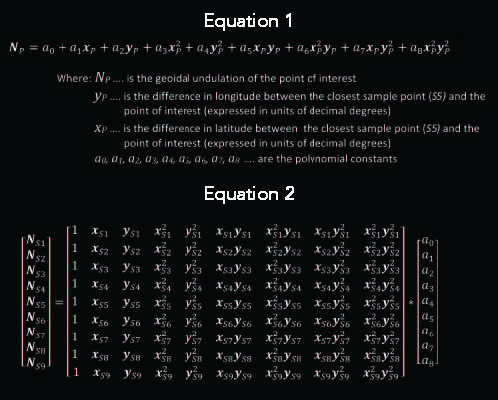
geoid model sample points to a point of interest and fits a fourth-order polynomial surface to these nine sample points (Figure 4). Then, by knowing the horizontal location of a point of interest within the polynomial surface, its geoidal undulation value can be determined. Unfortunately this interpolation technique is somewhat complex and requires the use of a system of linear equations. The fourth-order polynomial surface is defined by Equation [1].
In order to use this equation we first need to solve for the values of the polynomial constants (a0 …a8). This is accomplished by using the known geoidal undulation values along with the known latitude and longitude coordinates of the nine closest geoid model sample points (S1…S9). The known geoidal undulation for each sample point and the difference in latitude and longitude coordinates between each sample point and the central sample point (S5) are substituted into the previous equation, hence creating a system of nine equations. The system of equations expressed in matrix notation would take the form shown in Equation [2].
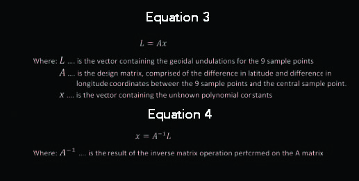
Expressing the previous formula in a generalized way, we would write Equation [3].
The solution to the vector of unknown polynomial constants would then be expressed as Equation [4].
Finally, once the polynomial constants have been solved, they are substituted back into the original polynomial equation, and they yield the practical interpolation equation for determining an accurate geoidal undulation for a point of interest.
The interpolation equation then requires only the difference in latitude (yP) and difference in longitude (xP) coordinates between a point of interest and the central sample point (S5) in order to solve the point of interest’s geoidal undulation. Depending on the geographic location and extent of a project area, there may be several neighboring polynomial interpolation surfaces that should be used for different regions of the project area. Each polynomial interpolation surface has an applicable geographic range of half the latitudinal and longitudinal spacing of the geoid model sample points.
For example, if a geoid model has sample points every one arcminute in both directions, then the applicable range of a single polynomial interpolation surface would be 30 arcseconds in both directions. This working range is centered on the closest sample point to the point of interest. Hence, as soon as a point of interest is farther than half the latitudinal or longitudinal geoid model spacing from the central sample point of the current polynomial interpolation surface (i.e., the S5 sample point), it is now closer to a different sample point, and thus a neighboring polynomial interpolation surface should be used. (An exception to this occurs when points of interest are very near a boundary [extent] of the geoid model. In this case the applicable range of a single interpolation surface may be extended, or different boundary value interpolation techniques could be used.)
Equations 1 and 2
Equations 3 and 4
Click here for a mathematical example for testing your skills in geoid model interpolation.
Here To Stay
Technology is sometimes viewed as being a double-edged sword, and geoid-model-based vertical datums would certainly support this view. Technology has now freed the surveying professional from the constraint of physically locating, verifying, and tying into demarcated benchmarks. While this should be viewed as a great technological advancement that will only benefit practitioners, the procedures that need to be followed to make this change a reality are quite radically different from the tried and true procedures of the past and present.
As a result, industry will most certainly be slow to adopt these technologically derived vertical datums unless people can be properly educated, informed, and trained. Even though using an automatic level to determine elevations is one of the simplest procedures within surveying, what is often overlooked is the physical state of the benchmarks themselves. In Canada, benchmarks are very rarely re-observed as part of a maintenance survey and are predominantly established near populated areas and highways for ease of access. This does not lend well to projects that are located in remote areas. Additionally, the cost to maintain the existing national network of benchmarks is extremely high. Hence, the quality of the published information with respect to a specific benchmark or local group of benchmarks can be inaccurate.
Geoid-model-based vertical datums overcome these two problems by providing a means of determining an accurate elevation virtually anywhere via GNSS positioning. They also make the determination and dissemination of vertical datum information and updates exponentially easier. This new type of vertical datum is certainly here to stay and should be adopted by surveying professionals as early as possible. Like all great technological advancements of the past, once the initial transitional hurdle is overcome, you will not be able to imagine your life without geoid-model-based vertical datums.