For nearly three decades, the foundational technology and design of precision levels for surveying has not changed much. It has not had to. Sometimes, when something is done right the best course is to stick with it.
Much has been written about the 50-year milestone of the Global Positioning System, while another 50-year milestone has been largely overlooked. It has been half a century since the technology of precision levels for surveying and geodesy reached what is widely considered to be its peak. And it has been nearly 30 years since automation was added to deliver such precision in a timely and effective manner.
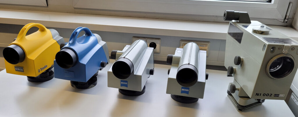
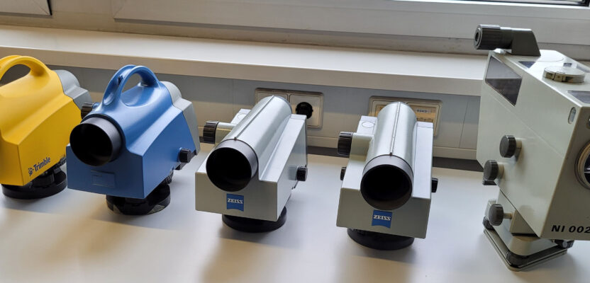
An evolution of digital levels, with the pioneering analog Zeiss Ni002 (right) and Trimble DiNi (left).
“This is one of the world’s most accurate levels,” said Torsten Kludas, managing director of Trimble Jena GmbH, referring to the Ni-002, released by Zeiss in 1973. “There is nothing like it today, and it is still used as a reference instrument.”
The advent of instruments like the Ni-002, that could achieve ± 0.2 mm/km in double-leveling ignited a flurry of research and development that would culminate two decades later in the form of the ubiquitous digital levels’ surveyors rely on today.
How did such instruments achieve this level of precision? Let’s back up a little and look at the history of precision surveying instruments.
The Modern Instrument Era
A wide variety of leveling methods have been employed throughout history. Giving way to the predominance of spirt levels (a sealed glass tube with an air bubble in alcohol). One of the earliest examples was introduced in 1661. For centuries there were many variations and configurations of bubbles and surveying instrument telescopes. In 1832 the “Y” style level was developed by English engineer William Gravatt. Later would come the easier-to-use “dumpy” or builders-style levels, auto, self-leveling, and tilting levels. Yet there were precision thresholds that would only be broken with a combination of advances in optics, machining, and scientific research.
The modern era for levels (and theodolites) came at the beginning of the 20th century based on work by the key figures of Carl Zeiss (the mechanic), Ernst Abbe (the scientist), Otto Schott (the glass chemist), and Heinrich Wild (the surveyor). From the collaborative environment these pioneers and others fostered at the optical systems manufacturer Zeiss in Jena, Germany, came what many consider the first truly modern surveying instruments.
In 1909, Zeiss introduced the Ni 1 level, which was one of the first instruments manufactured in serial production. Between 1920 and 1922, research and development for the Th1 theodolite (based on Heinrich Wild’s design) was complete, officially hitting the market in 1924 as the first optical theodolite from Carl Zeiss.

Torsten Kludas
Such instruments featured advanced and compact optics, such that telescopes did not have to be as long or heavy as in legacy instruments. Other features included glass circles, internal focusing telescopes (which were also reversible and rotatable), prismatic split coincidence bubbles, a cylindrical vertical axis, and more. Among these are foundational elements we still see in today’s total stations. Wild would go on to form his own company in Switzerland, that produced many famed instruments and begat a legacy of successive companies (e.g., Wild Heerbrugg and Leica Geosystems). He even went over to design instruments for a competitor, Kern.
The Zeiss brand grew into a broad family of technology, science, and manufacturing companies and spinoffs. This continues across many industry sectors, including innovations adopted by surveying instrument manufacturers like Trimble, Spectra Geospatial, and others.
The later 20th century brought a steady refining of the technology of levels, by Zeiss and other manufacturers, to include familiar brands such as Leica, Nikon, Topcon, Trimble, Pentax, and more. The Zeiss Ni-002, Kludas says, featured a unique reversing mirror compensator.
“We have here a two-reading possibility,” said Kludas, noting observation windows in the sides of the Ni-0002 he was demonstrating. “We can make a second face leveling measurement by flipping this mirror.”
This provided what is called a “quasi-absolute horizon,” the mean of the two readings being nearly independent of the distance between instrument and leveling rod. This also meant less of a need to balance foresight and backsight distances. With the optical-mechanical elements evolved to yield such high precisions, the next goal was to digitally automate field operation. What followed was incorporation of photogrammetry into the process, to read specially marked rods, and digital processing.
The Basics
Digital levels are comprised of relatively few components; nowhere near as electro-mechanically complex nor as densely packed with components as say, robotic total stations. They seem light by comparison. However, the amazing precision digital levels deliver comes from the application of sophisticated physics built into these highly refined and calibrated components.
The telescope components, the object and focusing lenses serve for operator sighting, but also to project the image of the coded rod to the CCD. For instance, on some digital levels, the CCD might only need to “see” 30 centimeters of the coded rod. While there is a circular bubble on the level, this is just to get it close enough for refinement by the compensator.
Unlike the compensators in total stations, that might be liquid surface, camera-based, with two axis mirrors and silicon oil, the DiNi for instance employs a pendulum. You can hear the click of the pendulum if you tilt it. The vertical axis needs to be finely machined, to provide a smooth and consistent motion. The rest of the housing contains the electronics boards, keyboard, display, data card slot and/or data port, and a battery compartment.
Externally, to ensure the best results, requires a high-quality tripod, and a coded Invar rod. These specialized rods typically have a core of Invar, which is a nickel–iron alloy with a very low coefficient of thermal expansion. The rod has a casing around it with the code printed on one or both sides.
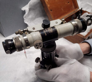
The Zeiss Ni 1 level, archived at the Deutsches Optisches Museum in Jena, Germany.
While the invar rod and code may remain consistent after many uses, the wear and tear on the rod assembly below the rod can become a factor. For these and many other reasons, the rod and level need to be checked regularly. There are simple office procedures for doing this, and many precision-leveling crews do this before each leveling campaign. Levels and many Invar rods delivered with calibration certificates (which must be noted for certain types of leveling, for instance to meet various national standards). Levels can be sent back to manufacturers for further calibration and re-certification. However, for rods there are few facilities that can recertify; it can sometimes cost more to ship a rod overseas for recertification than to buy a new one. With careful handling, storage, and transportation, Invar rods can last many years, as can the levels.
As noted, temperature is one of the external factors that affect performance. Others include the ambient illumination, particulate matter in the air, humidity, turbulence, vibration, unstable ground, etc. Guidelines for the most precise classes of leveling prescribe strict procedures and ancillary equipment. For instance, keep the level out of direct hot sun (umbrellas are recommended in some published guidelines), don’t set up or turn on pavement, use portable rod turning point “turtles.” Per some guidelines, turtles need to be over a certain weight, and you may need to use turning spikes pounded deep into soft ground, etc.
The U.S. Federal Geographic Data Committee Specifications and Procedures to Incorporate Electronic Digital/Bar-Code Leveling Systems details procedures/equipment requisite of higher order/class leveling and gives the performance specs that digital levels must meet. Fortunately, digital levels on the market can meet such specifications.

Internal components of the DiNi digital level. Source: Trimble Jena GmbH
Further, submission of levels to various agencies might have additional requirements; note keeping, minimum ties to control of a minimum order/class, temperature readings, etc. For instance, to submit levels for higher orders/classes, use of a thermistor is prescribed (a calibrated temperature sensor; with two external probes for reading high and low reading on the tripod).
Some good deep reading on the subject, examining the sources of systematic error, testing, and calibration is the doctoral thesis of Dr. Helmut Woschitz: “System Calibration of Digital Levels: Calibration Facility, Procedures and Results” (2003), and the related paper from the INGEO2002 Surveying Conference by Woschitz and Brunner.
Despite this seemingly large list of external and internal sources of systematic error, modern digital levels deliver high precision at or near the highest listed specifications (in most conditions) with simple best field practices, regular checks, and care of the equipment. Digital levels are very high precision but almost too sensitive in some cases. Users find that setting up the level on some bridges can be easily affected by the bounce and vibration from traffic and wind. And there are special procedures for shooting over bodies of water.
In Part Two, we will examine the evolution of a popular, modern digital level.