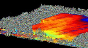
A raw point-cloud dataset showing wooded areas.
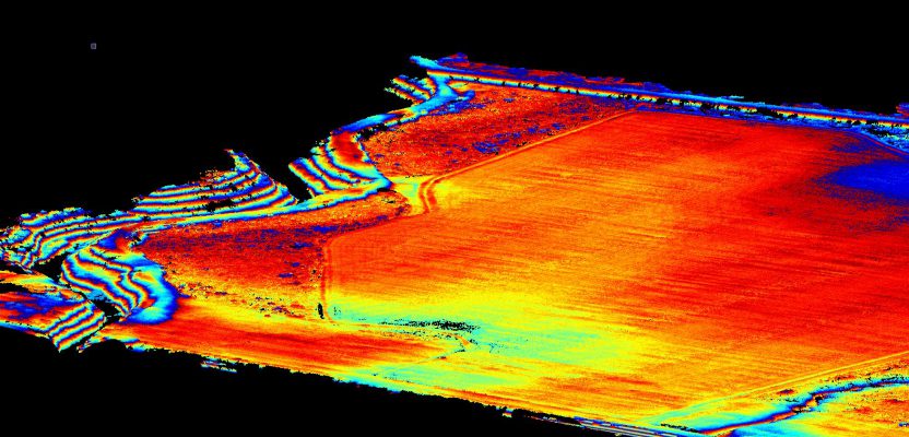
Image above: The same area as shown in the picture to the right with the ground extracted and the trees filtered out.
A construction/survey project proves that UAS-borne lidar can penetrate tree cover to yield accurate ground data with improved post-processing times compared to photogrammetric solutions.
I’m the VP of remote sensing at Morris P. Hebert, Inc. (MPH), an engineering, construction, and surveying services company based in Houma, Louisiana.
In late summer of 2016, our client was scheduled to begin a construction project and wanted to use the excess dirt from the project area to spread across an adjacent tract to bring the elevations above the current FEMA Base Flood Elevation. They hoped this would make it easier to obtain permits on any future projects in this area.
In order for them to come up with the best way to handle the excess dirt, they tasked MPH with performing an elevation survey of an approximately 340-acre tract.
MPH had received their FAA 333 exemption in October 2015 and had purchased a fixed-wing UAV photogrammetry solution earlier in 2016. MPH felt that, given the size of the project area, it would be a perfect opportunity to utilize aerial photogrammetry to capture the data quickly and accurately. The project area was flat, undeveloped, and mostly covered with tall grass.
Prior to performing the UAS survey, MPH had to coordinate with the client to have the grass cut to ensure the most accurate results from the survey. This coordination and grass-cutting effort added two weeks due to the contractor’s schedule and weather delays.
Once the grass was cut, MPH was able to perform the survey with our fixed-wing photogrammetry solution. MPH performed three flights at an altitude of 350-ft in order to cover the entire area and utilized eight ground control points.
Over 1400 images were captured and processed; this processing took approximately three full days. The processed point cloud data was brought into AutoCAD Civil3D in order to create 2-foot contours and perform volume calculations for the final deliverables.
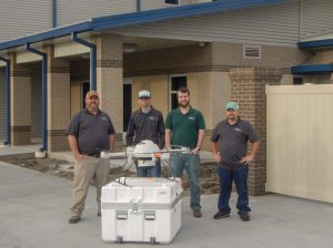
MPH remote sensing personnel, from left: Kiley Cressionie, pilot; Stuart Babin, pilot/project manager; Jonathan Morris, project manager; Cody Pisani, visual observer/technician. Not pictured: Lee Drennan, research and development.
New Lidar Survey
In the fall of 2018, the same client requested that we provide a similar deliverable for the remaining 680 acres immediately adjacent to the area that had been surveyed in 2016. Their goal was to collect sufficient data so that they could begin the planning, engineering, and design of additional infrastructure.
This new area was not only larger, but also contained different landscapes from the previous area. In addition to undeveloped land covered mostly with grass, it also contained wooded areas, developed land, and some significant elevation changes due to containment dikes, ditches, and waterways.
After performing a desktop analysis and revisiting the previous survey work adjacent to this project, we decided that performing a lidar survey would be the best path forward.
Lidar vs Photogrammetry
MPH decided that a UAS-borne lidar solution would be better suited for this area over a photogrammetric approach due to the existing site conditions and our experience gained from previous surveys. Of the 680 acres, approximately 100 acres were wooded, 100 acres were developed, and the remaining 480 acres were undeveloped land covered in brush and tall grass.
In order to gather accurate elevation data over the entire area, it would have been necessary to clear the wooded area and clear and cut the undeveloped areas. Clearing the wooded area was not feasible, and MPH learned from the previous project that having the undeveloped areas cleared and cut would add time and money to the overall project.
The photogrammetry survey option would have been approximately 20% cheaper, and the field work could have been accomplished faster, but it would have required coordination to get the lands cut and cleared to ensure the most accurate data possible.
The photogrammetry option would also have led to gaps in the data set of the wooded areas. MPH had calculated that the photogrammetry option would take approximately 10 flights (approximately two to three days in the field) at the lowest possible flying altitude (246-ft) with a Sony a7R 35-mm camera in order to produce the highest resolution dataset.
Since the photogrammetry option would provide only one return and would depend on the vegetation within the area, the high density had the best possible chance to return elevations from the natural ground and produce a dataset that would be comparable to accuracies expected with the lidar option.
In addition to performing the flights, multiple ground control points (GCP) were going to be surveyed for each flight. MPH anticipated using at least five GCPs for each flight, which would have added to the duration of the field work.
This color surface was made in Autodesk Civil3D from the extracted ground and filtered point-cloud dataset. The color elevation ranges are every 2 ft.
Choosing the Tech
MPH had recently purchased a Microdrone MDLiDAR system for another project and decided to utilize it on this project as well. The MDLiDAR package contains a SICK lidar unit and a Trimble APX-15 geo-referencing system. The SICK lidar is capable of scanning at a rate of 19,500 points/sec and would provide three separate returns (typically treetop and bare earth).
We decided that a point density of at least 50 pts/m2 would produce a deliverable that would meet the project needs. This would be accomplished by setting the flying parameters to a flying altitude of 60-m and a speed of 3.5 m/s.
Using these flying parameters, we estimated that it would take approximately 40 flights (approximately five days in the field) to cover the entire area. Due to the geo-referencing system on the MDLiDAR, the need for GCPs was greatly reduced, and data QA/QC could be performed much more efficiently with ground truthing points.
Even though the lidar solution would take more time in the field than the photogrammetry option, MPH felt that the data processing in the office would be faster and easier and would yield better deliverables. The photogrammetry software estimated that 10,000+ photos would be needed to cover the entire area; it could have taken weeks to process that amount of data. In contrast, the lidar option could produce point clouds from each flight in a matter of minutes. The point clouds from the lidar option would also be easier to manipulate and extract the ground from due to the multiple returns. The photogrammetry created point cloud would have required more cleanup and manipulation in order to get actual ground elevation.
Platform Selection Considerations
MPH decided to purchase a Microdrone MD4-1000 lidar unit after researching different rotary unmanned aerial systems for years. Since 2015 when we decided to get into unmanned aerial surveys, the industry has taken off at a rocket’s pace. Our biggest concern was that when we finally decided to pull the trigger on a rotary UAS, it would be outdated or something bigger and better would come out.
When it came to the fixed-wing solution for large-area mapping, we all felt like the solution that we purchased made sense because it was survey-grade accuracy and was being sold by a company whose products we have had more than 30 years of positive experience with.
After several product demos of different packages, we decided to move forward with the purchase of the mapping and inspection package in the fall of 2017.
It should be noted, however, that we were not particularly invested in purchasing the MDLiDAR package as soon as it came out. We wanted to ensure that specifications and data quality would meet our high expectations. Once the specifications were released, we compared them to other lidar sensors on the market. We also performed multiple demos of the product in conditions that would be considered less than ideal in order to ensure that we would be getting the results that we would need during real-world applications.
We were also interested in other aspects of the lidar package, such as the flight planning software, the overall integration of the system, and the workflow from post-flight to a corrected dataset. Since we had already been flying the MD4-1000 mapping package, we were familiar with flight planning/mission software and were impressed with how seamlessly the MDLiDAR was integrated into the software. This allowed us to purchase the system and put it to use on projects almost immediately with minimal training and/or downtime.
The workflow was a little different at first due to the fact that it involved two programs, MDLiDAR and POSPac, that we had minimal experience with. However, once we were able to process a couple of the demonstration flights, we found the processing to be easier and less time-consuming than a typical photogrammetric project.
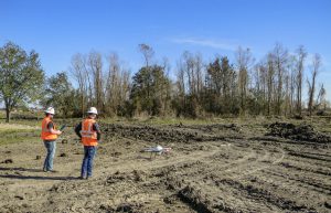
Jonathan Morris (operator) and Stuart Babin (VO) prepare to take-off with the Microdrone MD1000. The flight mission would be over undeveloped, wooded areas and areas undergoing site development activities.
Field Operations
The field operations for the project were pretty straightforward. Prior to mobilizing to the site, MPH performed a desktop analysis of the flight area to check for any specific airspace requirements, nearby airports/airfields, and any towers and/or other obstructions that may be present. There were: no restrictions on the airspace, three nearby private airfields, and some high voltage transmissions line towers that would need to be spotted and avoided while on site.
Prior to mobilization, MPH contacted the three private airfields as a courtesy to make them aware of the planned UAS activities and filed a NOTAM (Notice to Airmen) with the FAA since the area is sometimes frequented with low-flying inspection aircraft.
MPH pre-planned the flights needed to cover the area in the office in order to get an idea of the total amount of flights that would be needed.
MPH sent a two-man flight team with the MDLiDAR package, a laptop for downloading and field QA/QC, and a GPS-RTK base station to the site. Once on site, the flight team adjusted the pre-planned missions to take advantage of the existing site conditions and perform the survey in a more efficient manner.
Prior to flying any missions, an RTK base station was set up each morning to collect reference GNSS data at a 10 Hz interval. The base station needed to be monitored throughout the day to ensure that it was collecting data. The flight team decided to break the 680 acres into more manageable areas and would take a different area each day.
After each flight, the flight team would download the data to the laptop to perform a quick QA/QC and backup the flight data prior to performing the next flight. It ended up taking 35 total flights to cover the entire area. Other than normal issues with weather, etc., the data was collected successfully within the allowable time frame.
Post-processing
When it came to post-processing the collected data, MPH used a combination of Trimble Business Center, Trimble POSPac, and MD- LiDAR. Trimble Business Center was used to process the static data collected from the GPS-RTK base station and point cloud editing/filtering; the trajectories were processed in Trimble’s POS- Pac; and the point clouds were created in Microdrones’ MDLiDAR.
When the data was brought back to the office, the first step was to post-process the GPS-RTK base station data against local CORS sites to produce a survey-grade position for the reference point. Then each flight was processed in POSPac, which accurately fixes the trajectory of the aircraft by processing the MDLiDAR internal Applanix APX-15 IMU and GNSS data against the GNSS data collected from the GPS-RTK base station. This would create a flight trajectory file that is used within the MDLiDAR software.
Each flight produces individual data files for each survey line that is flown. When you combine these individual data files with the corrected flight trajectory file in the MDLiDAR software, it produces a point cloud dataset for each survey line.
For final output from the MDLiDAR software, MPH chose the LAS v. 1.40 point cloud format.
After all 35 flights were processed and exported from MDLiDAR software, there were a total of 175 individual LAS files. These files were combined into one file utilizing LASTools and then imported into TBC.
Once imported, MPH utilized ground extraction to remove trees, powerlines, etc., and performed manual clean up to ensure only the ground remained.
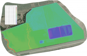
The modified point cloud was exported to Autodesk Recap so that it could be brought into Autodesk Civil 3D to create the final deliverables, which consisted of a plan view map with 2-ft contours, a 100-ft grid depicting spot elevations, and a drawing containing the modified point cloud down-sampled to 1-ft intervals.
The client was more than pleased with the final deliverables, especially the drawing with the point-cloud dataset as they were going to be able to use that for their site engineering and project development.