Beyond the electronic bubble: Integrating self-calibrating, magnetically immune tilt compensation in a high-precision GNSS rover.
This is not just another rover with an electronic bubble and tilt compensation. This new technology represents a genuinely significant step in the evolution of GNSS rovers.
We are presenting this look at—and inside—the Leica Geosystems’ GS18 T not as a product review per se (we encourage you to test drive one yourself and verify results). Instead, we focus on the story of a decade-long quest for sensor integration, the results of which provide a glimpse into the future of not only GNSS rovers, but also perhaps other surveying and mapping instruments to come.
The key differences between Leica Geosystems’ GS18 T’s tilt compensation and that of many other systems released recently is that it is does not rely on a magnetic compass, and it does not require the user to go through a calibration process.
It self-calibrates through an integration of the GNSS engine working in concert with MEMs based inertial measurement units (IMUs). You can start observing points as soon as you move to the first point, and you do not have to worry about leveling up the pole—at all
Not to be overlooked, the system has been designed specifically to mitigate the effects of working with satellites at low angles when the rover head is tilted.
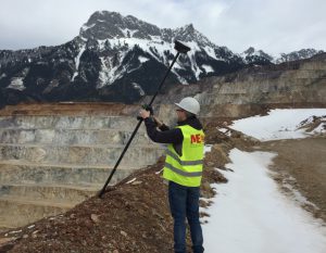
Safety is a key benefit of tilt compensation. One does not have to “plumb up” while standing on the edge of a steep drop-off, or as shown here on the edge of an open pit mine.
New and Legacy Tilt
Announced by Leica Geosystems at the September 2017 INTERGEO international exhibition and conference in Berlin, the GS18 T drew immediate attention and long lines to try one. We took it for a quick test drive and highlighted the GS18 T in a selection of significant product announcements from the show in our November 2017 edition.
Electronic bubbles and tilt compensation are not completely new developments, with compensators standard in many instruments, such as total stations, and with multi-sensor GNSS and IMUs having been in mobile systems for road, sea and air for many years. And tilt is not new to GNSS rovers, though this particular implementation is in many ways completely new.
While moderately popular and becoming standard on high-end rovers, the use of these functions has not caught on with many users. We hear the same points of pain and apprehensions about results that have made for a slow rollout of legacy tilt solutions (I guess we can now call them that).
As to the strengths of electronic bubbles and tilt compensation, I am an unabashed fan of these, even the early systems. In the right situation, an electronic bubble and tilt compensation can save a tremendous amount of time and allow you to take shots in places otherwise GNSS-unfriendly, such as under the edge of parked cars, inverts in catch basins and maintenance holes, dangerous edges of quarries and mines, under the edge of thick canopy, and up against buildings.
You can also use electronic bubbles to trigger shots automatically (when leveled to a tolerance you choose), to exclude shots out of pre-set tolerances. All this while not having to look at the bubble, allowing you to keep an eye to your surroundings, which improves safety.
On a project a few years ago, I took one of the early systems with an electronic bubble to topo a roadway ringing a reservoir, and a colleague took an equivalent system but with a conventional bubble. We set off in opposite directions. By the time we met on the other side of the reservoir, I had made it two-thirds of the way around and my colleague had made it one-third of the way around. My colleague is an efficient surveyor; the difference was in the capabilities of the instrument. The time stamps on the shots in the database showed the difference in time needed for each shot. In this instance I had only used the electronic bubble to trigger a shot when close enough to vertical. With a little pole finger balancing this did not take long. But I can imagine how much faster the survey would have gone with a GS18 T; I would not have had to level up at all, and I would not have had to recalibrate along the way.
But there are downsides. The electronic gyros and tilt sensors in older systems yield precise angles from vertical but rely mostly on an electronic compass for horizontal orientation. Not only do you need to go through often-cumbersome calibration routines, some with special jigs, but they are susceptible to magnetic disturbances such as heavy equipment and structures. Such systems do a pretty good job of warning you when you might need to recalibrate, but there is enough uncertainty to prevent many surveyors from fully embracing these technologies.
When I heard that Leica Geosystems had added, as they stated, “magnetically immune, self-calibrating tilt capabilities” to their newest GNSS rover, I wondered if they were just playing catch up, but I was quite mistaken. In an interview with the development team for this product, I found out that there was good reason for waiting to implement and that tilt was not the singular motivation behind the development of this device.
Faster

Bernhard Richter is the business director for GNSS at Leica Geosystems.
“The main thing we wanted to do for the user was to make measurements fast,” said Bernhard Richter, GNSS business director at Leica Geosystems.
We recently interviewed Richter and some of his Lecia Geosystems and Hexagon colleagues to find out how the GS18 T works and to hear the story of its development. There are, of course, elements that the team could not reveal, but what we did learn made so much sense, as did hearing about the origins of the eventual solution.
Richter said that the main motivation was to make the fastest rover they could, and that tilt compensation made sense to add, but, as he said, “[We] wanted to make it easier, to solve the common problems with tilt compensation, and reduce the typical errors. We have now released the GS18 T. The ‘T’ means tilt, as the first truly magnetically immune GNSS rover and calibration free.”
Richter explained that they followed four rules while developing the solution.
“Rule 1: We cannot control the magnetic field of the Earth. It varies a lot, and there are many magnetic hazards. Trucks and excavators have a big magnetic influence. We would not develop a magnetic-based system.
“Rule 2: [We want to] enable the user to measure as fast as possible without having to watch the bubble, no matter how much it is tilted from the vertical—even 30 to 40 degrees to get the antenna away from objects.
“Rule 3: [The user must] be able to take it out of the box and begin working immediately. With compass-based systems you need to calibrate. When tilted, we project the antenna phase center on the ground, this intersection as a circle. But to place the position on the circle we want this relative to true north—WGS84—and we will use GNSS and velocity to determine this angle.
“Rule 4. [We want to] develop a rapid ‘self-calibration’ that requires no additional user action. Once you start moving, as a normal part of your field work, you provide acceleration and GNSS orientation. This is the only calibration, and it is only needed to initialize direction. If you hold still it will eventually lose that calibration, but only a small amount of movement is required to re-calibrate rapidly. The calibration is constantly updated as you keep moving.”
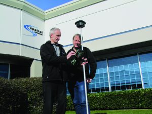
xyHt editor Gavin Schrock receives instruction on the GS18 T from Keith Belsham (on left) of Spatial Technologies, a Leica Geosystems distributor in Vancouver, British Columbia.
That last point might take a leap of faith for surveyors who have spent decades trying to hold the pole as still and level as possible. But the science behind precise (and in some ways superior) orientation from movement has been solved for other positioning and navigation systems for decades, and this has influenced the development of the GS18 T solution.
Mobile mapping, airborne mapping, and marine navigation systems benefit from the integration of multiple sensors: GNSS, accelerometers, gyros, airspeed, and velocity sensors. Consider the SPAN system from NovAtel (another Hexagon company). Such systems compute centimeter-grade positions for moving cameras, lidar units, and other sensors while taking heading, speed, pitch, yaw, roll, and in the case of marine systems, heave into account—all happening at highway speeds, plowing through rough seas, or zipping across the sky.
The challenge in doing this on a GNSS rover, says Richter, “is size. These [marine, airborne, mobile] systems are large. We cannot put in a large $20K gyroscope as accurate as one on an Airbus 320 on a rover. As part of Hexagon, we consulted with our partner NovAtel for some early things, but then we developed and produced all of our tilt sensors at Leica Geosystems.”
Due to proprietary information he could not disclose the full inner workings, only that some fundamentals were the same as these larger and more expensive systems. Key breakthroughs were in designing components in more compact forms.
When asked about the specific types and numbers of MEMS sensors in the GS18 T, Richter pointed out that these numbers don’t really tell the user anything about the quality and that numbers out of context should not be a marketing strategy. I agreed; the example of the sometimes humorous posturing in the industry over numbers of GNSS channels comes to mind.
A question pops up when surveyors talk about tilt solutions: How much is GNSS performance affected by a high degree of tilt? And does seeing only one partial side of the sky reduce the number of usable satellites? Richter said that solving this issue was key to the reliability of the tilt compensation. Leica Geosystems’ parent company, Hexagon, has many other subsidiaries that encompass a complete value chain for many of its products and solutions, subsidiaries that often help each other out. Here is where Leica Geosystems sought assistance from NovAtel in designing antenna improvements specifically to overcome this challenge. The rest is a bit of a trade secret. Richter points out that, aside from some initial assistance and help with the antenna, the GS18T is otherwise 100% Leica Geosystems.
I asked about the metal housing of the GS18 T, noticeably heavier than its GS16 predecessor. “The GS16 was designed to be a bit flexible, to absorb shock if dropped. For the inertial components, we needed them to be a bit more solidly mounted, [with] more room, and the aluminum housing provides shielding. We had to consider the WiFi, 400Mhz radio, Bluetooth, and modem inside; the aluminum housing is a very good shielding concept. There is also more room for an easily accessible data card slot (that our customers asked for), and we can hot swap batteries, the same batteries used in some of our other instruments.”
How Precise?
No matter how good the tilt computation, there will be some additional error, but not as much as you’d think. Richter said, “In the past, to measure a true north azimuth, people used cumbersome surveying methods: astronomic, or high-end gyros, separated GNSS observations, or total stations and GNSS together. Now with this tech, out of short movement, we get a true north azimuth better than a two degrees.”
I asked if this was simply the GNSS taking a series of positions and working out the differentials. No, he explained. “It is using velocity as well to provide an angle superior to that from a GNSS-only determined true north.”
At that point in the explanation a light bulb went off as to how this system could do the things claimed.
How much error comes from the tilt? “To determine the error, first consider the GNSS error, typically around 2cm,” said Richter. “The error of the tilt at 30 degrees would be about 1cm. But these are widely uncorrelated errors and not added together. According to laws of error propagation, the overall would only be about 10% more, so a total of 2.2 cm.”
I had read a bold statement in marketing materials that this solution might be “better than with a conventional bubble.” Richter said that of course, for instance, a static observation on good tripod would be best, but on a typical rover pole with a 20-minute, or even 8-minute bubble it would not.
“If you just measure topo points for a few epochs, there is no need any more to stay there,” Richter said. “This only averages the manual movement. The [GS18 T] is now faster and more accurate, and you can go down to 30 or more degrees with no drift.” I would later put this to the test.
But how do you know it’s working? Richter responded, “There is a green bubble on our precision symbol in the [Captivate] software and also a lighted symbol on the antenna. You see a tilted pole that turns from red to green. You can follow what is happening around you—you are not stuck looking at a bubble.”
Another area where such a system shines is in stakeout. Richter said, “In the old way you do an iterative process of holding the pole still at vertical and moving where it tells you. With this, the precise heading has augmented the reality. You just move the tip of the pole, the map rotates, and you just bring the pole tip in to the right location.”
What about setting tolerances? The user can do this as with a standard RTK, but Richter reiterated the goal of making operations easier. “We wanted to make this kind of black and white; it either works or does not. The user can set the tolerance of what they will accept, and our coordinate quality indicator incorporates both systems together, the GNSS plus additional error budget from tilt compensation.”
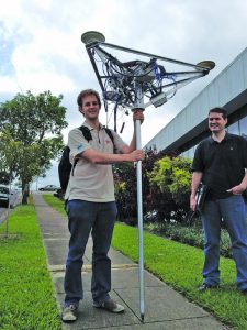
Damien Dusha of Leica Geosystems’ Brisbane facility (right) with one of the test “contraptions” constructed to prove that a hybridization of GNSS and multiple motion sensors could self calibrate and maintain precise tilt compensation. Targets were added for multiple total stations to verify precision.
Development
“We developed in a kind of startup environment, outside of the main project, so we could take more risks,” said Richter.
I asked if there were particular engineers who had the “light bulb” moment or solved key challenges in development of the GS18 T. Leica Geosystems and parent company Hexagon are adamant about emphasizing teamwork. Richter said, “We have a very bright team, and it is unfair to name just a few,” but that certain team members stood out at pivotal points in the design process.
“The motivation was to improve workflow, and the idea started about ten years ago – the first patents were filed then,” said Richter. “A very bright young guy in our Brisbane office, Dr Damien Dusha, was involved in some of those patents. He also built devices to test the tilt, to prove that it would work. He built some crazy designs, with multiple antennas, prisms, and four total stations to test the precision. Damien proved it would work.”
Proving an idea can work is one matter but “making it work 24/7,” as Richter put it, is another. “Another very bright guy, Dr. Matteo Carrera [GNSS algorithm engineer at Leica Geosystems, Switzerland] made that idea work.”
Like others on Leica Geosystems design teams, Carrera and Dusha have distinguished scientific backgrounds. Before joining the company, Carrera researched subjects the likes of gravitational physics and the relativistic effects on orbits and tracking of space vehicles.
Dusha, a software engineer for Leica Geosystems in Queensland, Australia, has a background in avionics and signal processing,, and his doctoral thesis was on a fusion of GNSS and computer vision for navigation. Rest assured that very bright people are designing that gear you purchase.
We had a glimpse of Leica Geosystems design and manufacturing during a past visit to their Heerbrugg, Switzerland facility. There is an environment of avoiding engineering and manufacturing compromises; this might equate to slightly higher prices. Indeed, there is an additional cost for the advanced features of the GS18 T over, say, the GS16, but end users seem to have no qualms about paying for quality and reputation.
The GNSS Engine
How much different is the GNSS aspect of the GS18 T from that of the GS16? “The GNSS engine is the same, but we had to solve tracking at a low angle. We have submitted a paper on this to FIG, and there is this absolutely new antenna,” said Richter.
I asked Richter about the “self-learning GNSS” feature, first announced for the GS16 two years ago and now also in the GS18 T. On this subject and multi-constellation solutions, I asked questions I often hear in discussions among surveyors. The how’s and why’s of integrating and using multi-constellations has been a subject of great interest, but also of a little confusion among end-users. This has been especially the case since Chinese Beidou (BDS) and European Galileo (GAL) satellites have started showing up amid the GPS and GLONASS (GLN) in user’s sky plots and GNSS solutions.
Richter responded, “There is no super easy message. In the case of self-learning, we mean this at two levels.”
“One is that the rover is evaluating which service to use. RTK, from a base or a network like HxGN SmartNet, or if the RTK corrections should become unavailable (maybe the radio or cell is lost) can switch to our L-band solution: SmartLink,” said Richter. SmartLink is Leica Geosystems’ PPP solution, being broadcast from L-Band geostationary satellites. This service was developed from Hexagon’s 2014 acquisition of Veripos, an already successful positioning service for maritime and terrestrial applications. SmartLink can automatically take over if the RTK source is lost or can be used standalone if no RTK sources are available. It can achieve near-RTK precisions almost anywhere in the world where a broadcasting satellite is in view.
The second level of the self-learning features, said Richter, “is RTK+, where the RTK adapts to the local conditions. Like in an urban canyon you may have two of four GPS in view that are bad, but three good Galileo, or some from different constellation. It chooses the best satellites out of many in view; sometimes it sees 24 or more now.”
With many new GNSS satellites being launched all the time, it might be years before the newer constellations are complete. So, users often wonder what combinations they can work with—for instance, the few GAL, BDS, and L5 satellites they see. Again, Richter noted that this is not a super-simple answer.
“Basically, three GPS satellites determine the coordinate unknowns, but you need to add one more satellite to solve the GPS clock offset. Adding a fifth or even more GPS satellites adds redundancy to the solution which generally leads to better positioning reliability. When mixing satellites from different constellations, one needs to keep in mind that each constellation has its own ‘timing’ bias that needs to be solved. Therefore, a constellation with 4 (GPS) + 1 (GLONASS) does not improve solution redundancy whereas 4+2, or 2+2+2, or 3+3 does. L5 is great because it adds even more information for solving other measurement-error sources like the ionosphere. There are many satellites in view now so there are usually more than enough to estimate an accurate position, and the [GS16 and GS18 T] continually evaluate the conditions and chooses the best solution.”
Galileo, in particular, has added a lot of options for developing improved solutions. Richter said, “It is nice that with every satellite you have E1, E5a, E5b, AltBOC. We could also track E6—super fantastic—we always use now four Galileo signals. It is becoming day or night whether you add Galileo or not.”
I noted that some consumer and “prosumer” GNSS device developers are opting to do only GPS+GAL solutions. I asked Richter if GLONASS is still “cool.” He responded, “With 24 GLONASS satellites up there, of course we want to use them.”
Test Drive
Our first brief encounter with the GS18T at INTERGEO 2017 prompted our desire to take one for an in-depth test drive. I recently visited Spatial Technologies, a Canadian provider of surveying and measurement solutions and an authorized Leica Geosystems distributor. Keith Belsham, branch manager for their Vancouver BC office, graciously provided hands-on instruction on the GS18 T, and we performed tests of its capabilities.
Spatial Technologies has an interesting story of its own, its evolution following that of construction and energy trends in multiple Canadian provinces over the years since the company’s inception.
“Spatial started in Calgary [Alberta] in 2002,” Belsham said. “When Leica Geosystems moved away from company [outlets], former Leica Geosystems employees started Spatial. There was a lot of activity in Alberta for the oil in the north, and we expanded to Edmonton [Alberta] and Vancouver.”
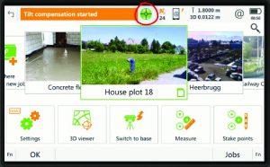
The “green bubble” in the Leica Captivate field collector software, along with a lighted symbol on the GS18 T receiver head, is the indicator of the calibration status of the electronic bubble, and tilt compensation can be accessed in the field or later in the office.
Initially. he says, the majority of their customer base was in surveying, but more recently, with a cooling of the energy sector in Alberta and a boom in construction in BC, they have found a rise in construction-related customers and machine control. Spatial now also offers the Leica iCON line of equipment specifically produced for the construction market.
The GS18 T is relatively new to the market and to distributors like Spatial. Belsham said that they’ve really had fun trying out the new features and demonstrating these to their customers. They’ve already had a few early adopters, and Keith introduced us to several.
Belsham also noted a trend in the surveying profession that xyHt has been following: surveyors seeking to diversify into providing services beyond boundary work, presumably in response to the uptick in construction and development and increased demand for these diversified services. This trend also has surveyors looking at a broader selection of surveying instruments and at more versatile instruments, like the MS60 multistation and now the GS18 T.
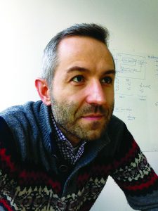
Dr. Matteo Carrera, GNSS algorithm engineer at Leica Geosystems, Switzerland.
Early adopters of the GS18 T, said Belsham, include the tech-savvy and those who are looking to upgrade. He noted that the reception among those who will actually do work—the field crews (the younger folks in particular)—is very positive, but that managers will probably take more time to see the value of paying extra for the GS18T. Belsham said he remembers the early days of EDMs where some folks would take out a tape measure because they were wary of results. Acceptance of this new solution could take time.
Many aspects of the operation of the GS18 T, Belsham said, are the same as with the GS16. If you connect to a network or a base, the default is to set the rover at a 5Hz update rate, even if the corrections transmissions are 1Hz. The GS18 T, like the GS16, can run as high as a 20Hz update rate, but that 5hz is sufficient for all but a few specialized uses. The base does not have to have to be a GS18 T; you can for instance use a GS16 (the tilt function on a base would be unnecessary). The system supports multi-constellation (GPS+GAL+GLN_BDS+QZS), and the international standard RTCM3.2-MSM format is fully supported.
We took the system outside and tried to see if we could “break” or otherwise confuse the tilt capabilities. As the solution relies on movement coupled with the GNSS, we tried common field-use motions and scenarios that we assumed would be a problem. We tried very hard but could not find many ways to mess with the GS18 T.
From the time we turned it on and connected to the local SmartNet mountpoint for RTK corrections, I had only to walk a few steps until the “green bubble” in the Captivate software (and the symbol on the antenna) indicated that the system had self-calibrated. The marketing statement about being able to work immediately, “right out of the box,” is essentially true.
I tried spinning the pole rapidly to see if it would lose the green bubble. It took a serious two-hand spin to finally do it. Normal rotation as you move around the site will not be a problem. I noted the position of multiple shots on a point while holding the rod plumb, then tilted over to 30 degrees and 45 degrees, and the position stayed roughly within a centimeter of the other shots. Only when I got it down to about 60 degrees did I see a significant variance. We twisted the pole all over the place and saw little or no variance. (Someone has already dubbed this the “drunken rod-person dance.”)
The rover loses the green bubble if you hold the pole perfectly still for about 20 seconds, but sometimes it was longer. We had been told that you need to walk a few meters to re-initialize the calibration, but we found that moving the antenna only as much as a meter brought the green bubble back and, on a few occasions, it took only a tilt of the pole.
After the tests with Belsham at Spatial Technologies, I spent a pleasant day driving around Vancouver looking for scenarios to test: up against walls, tiled out from the base of poles, trees, under the edge of cars, next to different multipath hazards. By comparing taped offsets, I could see that both the GNSS and tilt compensated solutions were quite solid. I retuned the rover to Belsham and reported that I was slightly disappointed that I could not find a way to fool it.
It is probably obvious that I am impressed by this new system, but I would encourage you to try one and come to your own conclusions. While I am already impressed with electronic bubbles and tilt compensation in GNSS rovers in general, this particular implementation—magnetically immune and self-calibrating—is a truly new step. It is a geek treat to be sure, but I also reflected on many hours of struggling with legacy rovers and how much faster and efficient GNSS surveying could have been had this solution been available years ago.
One statement by Bernhard Richter raised my eyebrows. At the conclusion of the interview he stated, “This is only the beginning of our sensor integration.”
An Early Adopter
Greg Maier, survey coordinator for the City of Kelowna, was looking to upgrade his GPS equipment and had just heard of Leica Geosystems’ new GS18 T GNSS rover. Initially intrigued by the new features, as an early adopter of this new system, Maier soon found substantial benefits beyond those originally envisioned.
The City of Kelowna in British Columbia, Canada, is a growing city of 130,000 along Lake Okanagan in the south-central region of the province. Kelowna, coincidently is home to the headquarters of MicroSurvey (another Hexagon company).
As survey coordinator, Maier and his crews are responsible for providing cost-effective surveying services for the city, services that encompass all things civil: transportation, drainage, utility and facility engineering projects, and as-built surveys.
“It was time to upgrade,” said Maier in a recent interview with xyHt. “We are traditionally a Leica Geosystems outfit, so of course it is easy for us to keep with the same brand, software we are familiar with and having other existing Leica Geosystems gear and accessories. But we always look around to see what is out there.”
Maier explained the process of evaluating new equipment. “Different vendors show us the latest and greatest, and sometimes you can say ‘that’s nice.’ But they tell you about some other features, and you say, ‘Well, that’s great but is it really going to work?’ Or, ‘Is it a selling point?’
“But in this case with the tilt thing, when our tech sales rep told us about it, I wasn’t sure what to think of it,” said Maier. “How is it really going to help us? I really had to think.”
Online videos were the key selling point, Maier said. “The videos showed direct examples of work that we do that could use the tilt capabilities.”
“For us it was not so much that it is faster, which is great. We work for the city and we have to get stuff done as efficiently as we can, but our biggest concern is around safety,” said Maier. “With this rover we do not have to concentrate on ‘bubbling up’; we can keep an eye on traffic and more of the world going on around us. That is huge for us.”
Maier added, “Great that it is faster; Leica Geosystems is suggesting that it is 20% faster because you do not have to bubble up—and in our experience that is a realistic estimate—but my point back to my managers was that it is a safer device for us to use. We can capture the data we need to capture, for instance, out in roadways, but we can do it safely. Instead of standing out on a paint line, we can stand off to the side with just the tip of the pole in the roadway, having traffic going by us in the lane of traffic but still having a better physical separation.”
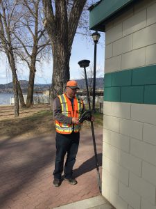
Greg Maier, survey coordinator with the City of Kelowna BC, Canada notes the utility of the tilt compensation for working around buildings, reaching under the edges of cars, and down in culverts; shots that prior to using the GS18 T might have required using offsets or a total station.
In the early days of using their new system, Maier and his crew had identified more scenarios where the tilt compensation enables measurements that might have otherwise called for an offset or setting up a total station. “We’ve been tilting it all over the place, even up to 45 degrees to capture a pipe inside a culvert at one of our landfill sites. We’ve done pipe inverts building offsets, and around trees.”
Maier and his crew have been enjoying the benefits of the upgrades in a general sense, as well. “It keeps surprising us. Not only the hardware itself but because we got the latest Captivate software—that alone was a quantum step for us. We went from the [Leica Geosystems 1200 system] to Captivate, but we also have [Viva software] on a total station. We now have two of these GS18 Ts and a Nova MS60 total station.”
The steady progress in development of surveying software and hardware—across the industry—is something that Maier and many surveyors appreciate. “It is like anything else—it is the next generation—you can follow the progress and they’ve added in wish-list items. You are in the field and you scratch your head and think, ‘Hey, it would be nice if the software did this,’ and lo and behold now it can do that.”
Like many surveying and engineering outfits, the City of Kelowna, out of necessity, must be strategic in their upgrades. Maier said, “For example, we are a Civil3D shop, and we don’t always upgrade to every version, but instead every two releases. You look at updates and you can see where they are going logically, but sometimes you don’t always agree with it. There will always be tools in there you might not use, but a lot of it makes sense and a lot of it increases your efficiency and productivity.”
Maier provided examples. “More and more these days we load a lot of our alignments and design surfaces from Civil3D to the instrument [via XML]. We were doing it with our [Viva software] and Captivate is just that much better—it is easier to use.”
But Maier also urged caution in adopting automation, much along the lines of the saying “with great power comes great responsibility.” Maier said, “In some ways it is a bit more dangerous because you have to be aware of what it is doing to make sure you do not make an error, which can turn a day’s work into garbage. “
Maier’s crew typically uses their GS18 Ts in single-base mode using a local reference station that is part of HxGN SmartNet, a real-time corrections service. I asked Maier if he was confident in both the GNSS results of the GS18 T and the tilt compensation.
He replied, “Yes, the device takes the shot at pole tip, and you are off and running with an accurate shot.”
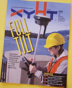
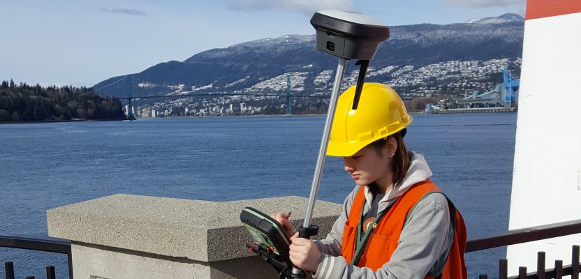
This article appears in the July 2018 print issue of xyHt Magazine. Survey field assistant performing a topographic survey with the GS18 T in Vancouver BC.