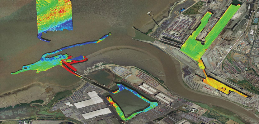
Interferometric sonars are providing a new tool for the hydrographic surveyor in shallow to medium-depth water applications.
As we begin to return to normalcy after the deepest recession of most of our lifetimes, many ports, coastal authorities, and inland waterways are starting to look at infrastructure projects that have been kept on hold, and they are beginning the process of investing in future-proofing their assets. The starting point for many of these will be to determine the depth of the water within their jurisdiction and ensuring that it remains navigable.
Traditionally, this type of activity was undertaken using a basic single-beam echo sounder running parallel survey lines to produce a lattice of depth measurements, or spot depths. Following the advent of multibeam echo sounder technology, many organizations have adopted this new technique, but it has its limitations.s we begin to return to normalcy after the deepest recessionof most of our lifetimes, many ports, coastal authorities, and inland waterways are starting to look at infrastructure projects that have been kept on hold, and they are beginning the process of investing in future-proofing their assets. The starting point for many of these will be to determine the depth of the water within their jurisdiction and ensuring that it remains navigable.
The disadvantage of using a conventional multibeam echo sounder, which is designed for ocean surveys, is that in shallow waters the angle of coverage is very narrow. The result is that traditional multibeam surveying in shallow waterways or ports takes a very long time as many lines are required to ensure 100% bottom coverage.
However, the introduction of a newer multibeam technology—interferometric sonar—has revolutionized the thinking in this field, and a complete port or inlet can now be surveyed quickly from a small vessel.
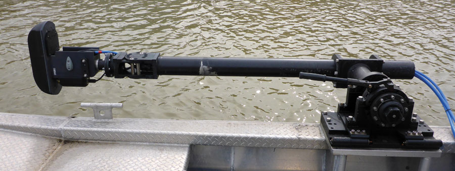
A typical interferometric sonar system mount onboard a small survey vessel.
Interferometric Sonars
Interferometric sonars, sometimes referred to as phase-measuring multibeam systems, use a completely different transducer layout to those of their deep-water namesakes. Instead of creating many beams in both transmit and receive mode, these systems transmit just one beam, identical to that transmitted by sidescan sonars.
This beam is very wide in the vertical direction and covers a span from immediately underneath the vessel (nadir) all the way around to the water surface on both sides of the vessel. The effective coverage angle can be up to 240 degrees in total, although it is inherently limited by the boundary of the water surface.
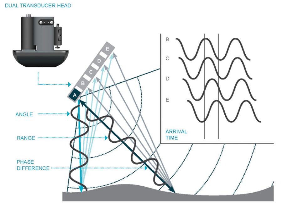
The phase difference detected by parallel receive arrays reflected from the same point on the seabed allows the target angle to be accurately calculated.
In the fore and aft direction this beam is very narrow, typically less that one degree, but the system can transmit and sample return echoes very quickly, creating swathes of depth points at up to 30 times a second.
The art of the system lies in its receive array where a bank of horizontally adjacent transducers measure very subtle differences in the phase of the return signal from each given point on the seabed. This phase difference gives a direction, and the two-way travel time of the sound wave gives a distance. Combining these gives the exact location of each point.
Because the system can sample data at a phenomenally fast rate, the number of sample points for each swath typically numbers in the thousands, thus enabling very accurate depth readings to be calculated for each of these points.
As an additional benefit, this fast sample rate, when converted to a distance using the prevailing speed of sound, maintains the system’s high across-track resolution even at the extremes of the swath, so there is no blurring effect at wide ranges that are apparent with older “beam-forming” systems.
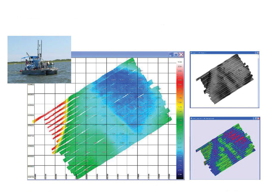
Constant 40 meter line pacing in 2 meters of water, between Fire Island and Long Island, New York. Data courtesy of University of Rhode Island.
Peripheral Measurements
Of course, in order to map the seabed as accurately as this, it is necessary to determine the vessel’s location, orientation (heading, pitch, roll), and heave. In addition, the speed of sound profile from the transducer down to the bottom surface needs to be measured and monitored, as different temperature layers within the body of water can cause the sound waves to be reflected and refracted. To do this, a range of additional sensors are deployed and connected to the sonar.
It is essential that all these peripheral measurements relate to the transducer face. To ensure this, an underwater motion sensor can be attached to the transducer mount alongside a sound velocity sensor, and these are typically all deployed on the end of a sturdy pole over the side of the survey vessel. To determine the vessel position and heading, a dual antenna GNSS receiver can be mounted on the top of this pole. Mounting the sensors in this way can reduce the risk of mistakes due to incorrectly measuring offsets between the sensors.
Deployment Vessels
Because the technology employed and the method used to transmit and receive does not need any additional electronics within the transducer assembly, the transducers themselves are lightweight and portable and ideal for use on small harbor launches. These systems have even been deployed successfully from rigid-inflatable boats as well as AUVs and ROVs.
For extremely shallow environments where it might even be difficult to maneuver a small boat, it is possible to use a remote-controlled vessel with the system and all its sensors pre-installed. The data can be stored on board and transmitted over a radio link to monitor the survey progress.
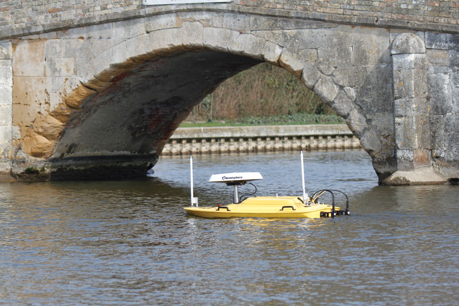
A remote-controlled
survey vessel uses interferometric sonar in very shallow water.
In very shallow waters, these systems provide their best performance. In terms of multiples of water depth, the coverage increases as the depth decreases, so it is possible when working in depths of less than 5 meters to obtain a swath width of 50 meters, or 10 times the depth.
In the example shown above, the line spacing was 40 meters but the water depth only 2 meters, so for the majority of the survey area 20 times water depth was the achieved.
Georeferencing
As mentioned above, these systems utilize a sidescan-like transmit beam pattern, so it is possible to see true sidescan data in real time, and because they employ accurate peripheral sensors and positioning equipment the sidescan images are geo-referenced. This is another beneficial side effect of these remarkable systems.
Sonar systems for hydrographic surveying have come a long way in a very short space of time, and new concepts, faster processors, and modern materials are driving this technology forward at an ever increasing pace. Intereferometic sonars are an example of this trend and provide a new tool for the hydrographic surveyor to use in shallow- to medium-water applications.