Six companies collaborate on a project to bury fiber optic cables under the Scottish seabed, stitching segments using hydrography, bathymetry, and surveying.

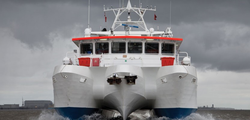
The 90-ft. Bibby Tethra is designed for maximum stability.
On land, surveyors face challenges due to rough terrain, human activity, weather, and more. Usually, however, the ground beneath their tripods doesn’t move, they can physically occupy positions, and the air between them and their targets is transparent.
Hydrographers and bathymeters, by contrast, work on vessels that are constantly rolling, pitching, yawing, heaving, swaying, and surging, due to waves, currents, and winds. Their view of the bottom is impeded by tens, hundreds, or thousands of feet of water, sometimes turbid. Occupying a position would require diving with scuba gear, a submersible, or a submarine. Besides, GPS signals don’t travel underwater! On land, surveyors face challenges due to rough terrain, human activity, weather, and more. Usually, however, the ground beneath their tripods doesn’t move, they can physically occupy positions, and the air between them and their targets is transparent.
Additionally, ships that can carry large sonar systems cannot navigate in very shallow waters, and small vessels that can navigate those waters cannot carry that large equipment. A recent bottom survey project in the waters off the coast of Scotland’s western islands faced all of these challenges, plus an additional one: stitching together seven survey segments for each of 20 routes.
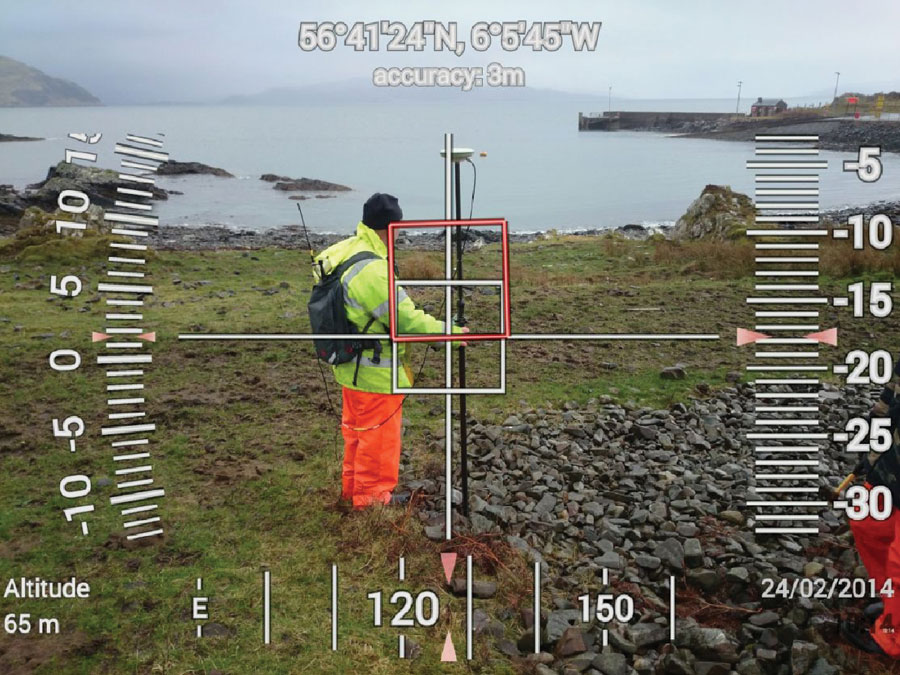
Surveying a cable landing point near the village of Kilchoan.
Bibby Hydromap
Bibby Hydromap, established in 1997 as Osiris and renamed in 2014, serves a broad range of clients, from oil and gas to offshore wind, marine aggregates, and subsea cables, providing high-resolution shallow water surveys.
“We’re typically involved throughout a project’s life cycle, from the early recon all the way to construction, monitoring, and inspection,” says Heather Carrigher, the company’s marketing manager. Its fleet of five coastal vessels is equipped with advanced survey and positioning equipment.
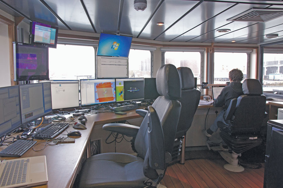
The survey lab on the Bibby Athena, where bathymetry data is being acquired by the full rate dual head Teledyne RESON multibeam echosounder, comprising two independent systems in each hull.
A contract with Teledyne Reson, a manufacturer of sonar technology, keeps it equipped with the latest hardware and software. “The resolution keeps increasing,” says Gustav Petterson, the company’s survey manager.
In addition to using sonar devices to measure depths, Bibby Hydromap uses magnetometers to detect ferrous metals, sub-bottom profilers to collect shallow seismic data, and equipment and sensors to acquire deeper seismic data and conduct environmental monitoring.
“We also use ROVs [remotely-operated vehicles] and AUVs [autonomous underwater vehicles] on occasion, including our newly launched dynamic remotely operated platform, d’ROP,” says Petterson.
“We developed the platform with a company named Hydrobotics,” says Carrigher. “We couldn’t find a system that did everything that we needed in terms of survey in the ROV world, so we decided to build our own. The platform is capable of supporting whatever sensor we want to deploy.” The company’s two offshore catamarans can deploy an array of up to five towed magnetometers, mainly used to detect unexploded ordnance.
Bibby Hydromap faces many challenges in its work. “We are often working in very shallow water, with limited clearance between the sensor and the seabed,” says Carrigher. “On top of that, in a shallow-water environment, we often have strong currents running.”
Additionally, it may have to steer the beams from the multibeam echo-sounder under the rig to get better coverage, explains Tom Davenport, the company’s principal surveyor. “The challenge is to keep the vessel on the line while the towed equipment is being pushed to the side.”
“Environmental conditions cause us more issues than anything else,” says Carrigher, “and it’s our job to design the survey spread to ensure that we can overcome adverse conditions and acquire quality data. The weather is an obvious example of this, and serious weather conditions can stop the program dead and lead to much additional cost and time delay.
“One simple way in which we have addressed this is our innovative vessel design, particularly with our flagships Bibby Tethra and Bibby Athena. Both vessels feature the semi-SWATH (Small Waterplane Area Twin Hull) hull design, which minimizes the effect of heave on the vessel, providing a stable platform for survey, and maximizes the weather window.”
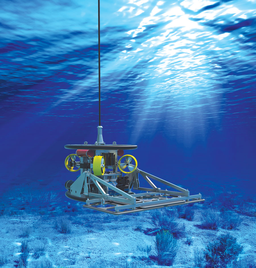
Bibby HydroMap’s dynamic Remotely Operated Survey Platform (d’ROP).
One Project, Six Companies
As part of its effort to make Scotland’s Highlands & Islands region more economically competitive, the Highlands & Islands Enterprise (HIE), a public agency, wants to dramatically improve the region’s digital connectivity and get broadband to some of the lesser-populated areas of the United Kingdom. To this end, HIE contracted with British Telecommunications (BT) to install a new fiber optic network consisting of 20 cables connecting many of Scotland’s western islands, up to Orkney, off the western and northern Scottish coast. The longest one is 79 km (49 miles), and the total length for all of them is about 380 km (236 miles).
In turn, BT contracted with Global Marine Services Limited to
- study the risks along each of the network’s routes based on internet research and visits to some of the sites (a “desktop study”),
- conduct a cable route hydrographic survey,
- assess where best to bury the fiber optic cable,
- engineer the route, and
- supply the cable.
Global Marine then subcontracted the survey to Bibby Hydromap, a British company, and the cable supply to Nexans, a Norwegian manufacturer. BT also contracted directly with British company A2Sea to do the terrestrial cable joints and with French cable installation company Orange Marine to physically install the cable that Global Marine engineered and designed.
Global Marine worked on this project with Bibby Hydromap (see above), then called Osiris, from January to July 2014. “We worked with them to undertake the cable route survey for the project, which involved a terrestrial topographic survey of all of the landing points and then an end-to-end marine survey for each of those 20 cables across the Scottish islands,” says Stuart Wilson, route engineering manager at Global Marine.
Avoiding a Costly Error
The difference in trenching sand and clay versus hitting rock could be a costly error. Stuart Wilson, route engineering manager at Global Marine, explains how they avoid this.
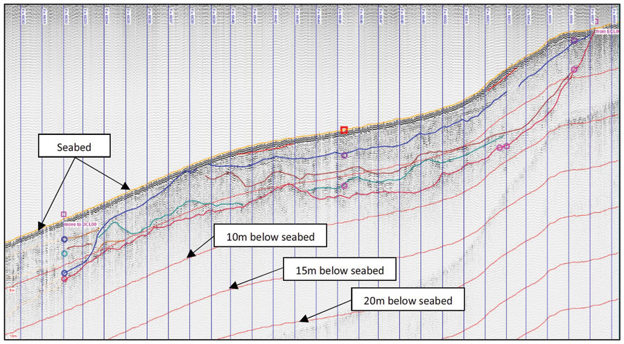
A profile of seabed layers from a sub-bottom profiler.
“The sub-bottom profiler is probably the most powerful of the acoustic tools. It sends a loud signal that penetrates the shallowest layers of the seabed. […] From the return […], it can determine the geological boundaries between the different layers.
“If you have a sandy infill in a channel with underlying bedrock, you can determine the depths and the shape of the profile of that channel where the infill has occurred so that you can determine how deep a sand layer you may have and, therefore, […] determine how deep you may be able to bury the cable. It gives you a profile view of the seabed and the geology in the shallowest depths.
“We are not really interested in anything that is below about 2 m deep underneath the seabed, because we are not looking at burying a cable deeper than a couple of meters maximum and in most cases around a meter. We are interested in the type of soils found in the top meter or two layer to see how deep a sandy seabed bottom is before it reaches either a harder layer with rock or some kind of very stiff clay.”
Ships and Sensors
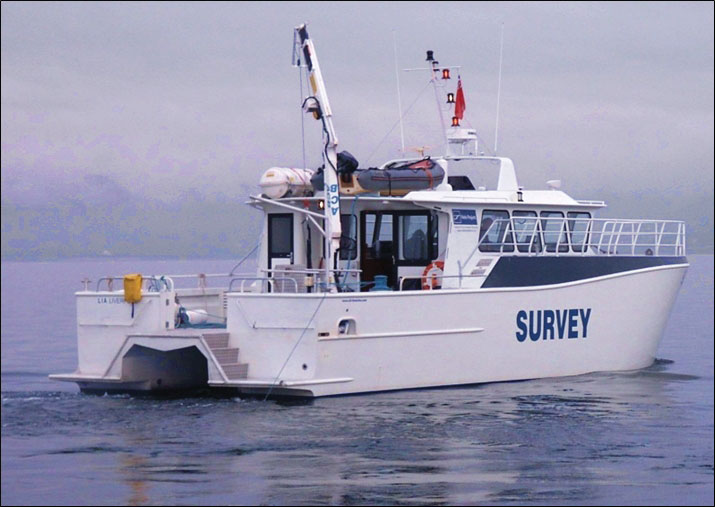
The 50-ft. Lia is able to run for extended periods at very low speed.
To conduct the survey, Global Marine used five of Bibby Hydromap’s vessels, including a small rigid inflatable boat to try to cover the section with very shallow water. The 27.5 m Bibby Tethra, the largest of those vessels, did most of the deeper water work, up to a depth of about 190 m, operating around the clock. For the in-shore sections, from about 20 m to 4 m, the smaller vessels Proteus and Lia conducted daytime operations, docking each evening. Bibby Hydromap also chartered the Neptune, a third-party vessel, and used it to conduct all of the required geotechnical sampling.
“We used multibeam echo sounders, side-scan sonar, sub-bottom profilers, magnetometers, and underwater cameras to get footage near the landing points,” Wilson recalls. These sensors can be deployed in a variety of ways. The multibeam echo sounder is normally mounted on the vessel’s hull or on a pole that’s fixed to it. The rest of the tools are normally towed behind the vessel on a cable. The side-scan sonar and the magnetometer have a towfish design, which allows them to be flown at depth, typically only about 20 m off the seabed.
The position of the vessel is determined using differential GPS, then an ultra short baseline system determines the underwater offset of the towed sensors, using an HPR (hydroacoustic position reference) pole that sticks out below the vessel and a beacon fixed to the sensor. Several sensors on board the vessel adjust the multibeams for the hull’s heave, pitch, and roll.
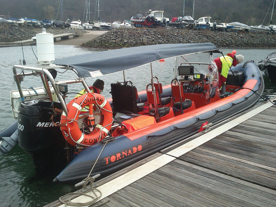
A rigid inflatable boat used to survey in very shallow water.
“We try, where possible, to avoid having to use divers to do any of the survey work, particularly in the very shallow areas, which means that we have to have extremely shallow-drafted vessels to try to get into the shallowest areas,” Wilson explains.
“We used the tidal ranges to help us do that, because the tidal range in Scotland’s western islands up to Orkney is quite large, in the order of maybe 3 m or 4 m. So, on high water on a spring tide, we could map using a rigid inflatable boat that we had, which would get into areas with a draft of maybe 0.5 m. Then, at low tide, using the topographic survey, we could get overlap on those data sets.”
The only disadvantage of using that boat, Wilson points out, is that it cannot carry a multibeam system and a sub-bottom profiler like the larger vessels, which limits the type of soundings it could take. However, it did have a single-beam echo sounder, a side-scan sonar, and a small underwater video camera, suspended from a cable.
“We also undertook probing from the rigid inflatable boat with a steel probe to try to determine the depths of sediments in these areas where we did not have a record from a sub-bottom profiler,” says Wilson.
Choosing the Routes
“Worldwide, by far the main risks to any submarine cables are through fishing activities and ships anchoring,” Wilson explains. “Fishing is pretty much ubiquitous across the whole of Scotland’s western islands in some form. So, as part of the desk study, we undertook an analysis of where most of the fishing activity was going on, using AIS and VMS [automatic identification system and vessel monitoring system] data.” To also avoid areas where vessels were anchoring, they reviewed navigational charts and consulted locals during their site visits.

Underwater video gives route engineers confirmation of data so they can determine how to protect the cable close to the shore
To best protect the cables, Global Marine wanted to bury them along the whole of their route in the marine sections. Therefore, after completing the spatial analysis, it tried to find areas within their survey corridors, which are roughly 500 m wide, where the seabed was less likely to abrade the cable and would allow them to bury it. “So, we were looking for soft sands and clays, rather than rocky outcrops and reefs,” says Wilson.
To this end, after completing the geophysical survey, Global Marine performed vibrocoring and geotechnical cone penetration tests, to ground-truth the results from the side-scan sonar and the sub-bottom profiler. It then tested the bottom samples for shear strength and particle size distribution and produced a burial assessment report specifying the required and achievable burial depths along each of the cable routes.
Finding Hazards Burial Tool
Global Marine was intent on identifying all seabed objects larger than 0.5 m in any dimension—whether they be rocks or pieces of wreckage—because they could present a hazard to the burial tool. They also wanted to determine the positional accuracy of some existing records.
“For many of these routes, there are other cables already there, and it is obviously very important for us to determine exactly where they are now,” says Wilson. “We do that using a magnetometer. We run maybe five magnetometry lines across a suspected cable line that is already in place and pick up where they are using that and then interpolate between those five positions to give us a line for that particular cable. We are looking to position that to within a meter of its recorded position.”
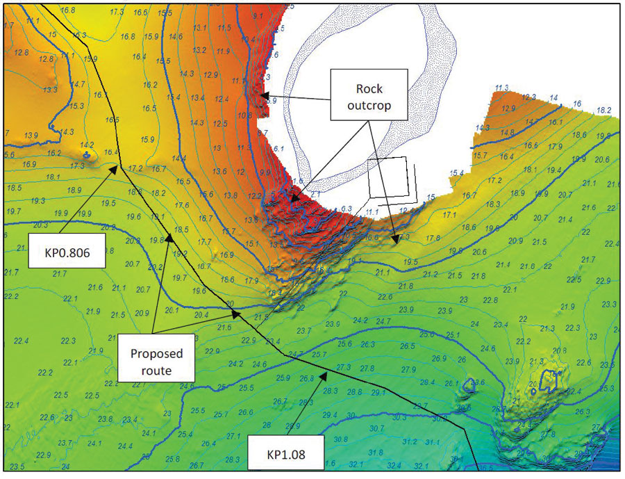
Finding the safest routes for cables requires accurate, high-resolution bathymetry.
Challenges
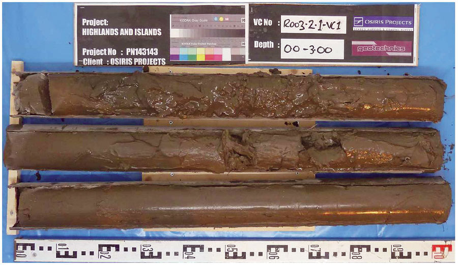
A vibracore system collects core samples of underwater sediments.
Probably the hardest part of the project, according to Wilson, was managing the survey program and stitching together the data sets from each vessel to produce end-to-end data sets that Global Marine could then use to do its route engineering work. For each of the 20 cables, it captured survey data in seven sections:
- at each of its two landings;
- at each end, from 0 m to about 5 m of water depth, captured by the rigid inflatable boat;
- at each end, between 5 m and about 20 m, captured by the smaller, inshore vessel; and
- the portion in-between, from 20 m to the maximum depth of the route.
“That is quite an arduous task when you then have 20 of those to do and they all have to be corrected for tidal fluctuations and quality controlled. Normally, we’d have, maybe, two or three segments where we land at maybe two or three sites with some quite large marine sections in-between,” says Wilson.
The number of companies involved in this venture and the range of technologies it employed reflected the complexity of the task. It was completed in 2014, and all the cables are now installed under the sea bottom, safe from ship anchors and fishing nets. While the detailed bottom charts produced in the course of this survey will greatly aid with future cable-laying along the same routes, the project also advanced the development of bathymetric and hydrographic techniques for use throughout the world’s oceans.
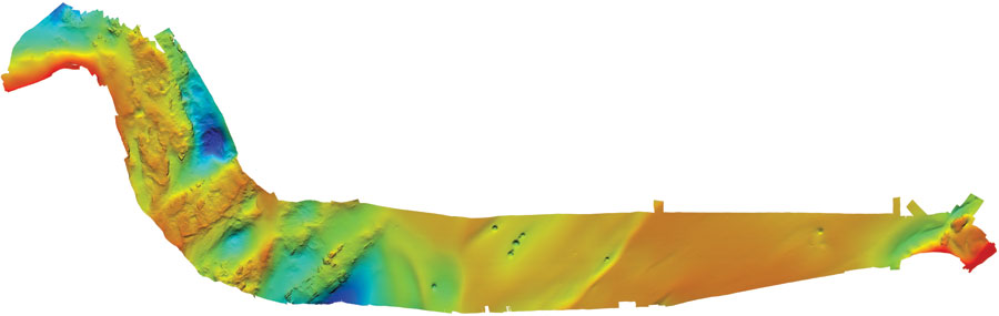
A bathymetric map of a cable route (with colors indicating water depth), produced using a Teledyne Reson 7125 SV2.