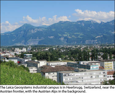
 “In the manufacture of glass for precision optics, if the glass is cooled too quickly there will be stress in the glass,” explained Hans Weinbuch of Leica Geosystems. He spoke to me during a tour of Swiss Optics, a primary supplier for Leica Geosystems and co-located at the Leica Geosystems campus in Heerbrugg, Switzerland. “The glass must be cooled over days or weeks in molds that are at the temperature of the molten glass” in some cases. Weinbuch added, “Stress in glass would make it unsuitable for precision optics.”
I had asked Weinbuch if we could follow the path of Leica Geosystems’ new MS50 MultiStation—all of the steps it goes through before reaching your tripod. Having started working for Leica Geosystems (formerly WILD) in 1956, Weinbuch has seen tremendous changes in the industry, but also, he noted, a consistency in the standards for all of the varied instruments manufactured by Leica Geosystems over the years.
Modern surveying instruments are among the most sophisticated and precise measurement devices in the world. Certainly, there are metrology instruments that work in the realm of microns, but few are designed to withstand the rigors of harsh weather and general day-to-day abuse of surveying field use. Customers are also among the most discerning and demanding; I’ve heard it said that surveyors could be handed golden eggs and they’d complain of imperfections in the shape.
Regarding the long lineage of Wild and Leica Geosystems instruments, their reputation sometimes gets characterized with respectful but humorous overtones: “the Swiss Miss is always right” and “built by Alpine elves.” There are also tales of long apprenticeships and manuals describing the process of installing every individual screw. I wanted to see the whole process, from subassemblies and optics to the testing and certification.
Path to Precision
 Swiss Optics divested from Leica Geosystems in 2004, and it is one of the former subsidiaries of Leica Geosystems that remain on the same factory campus and continues to produce high-precision products, with Leica Geosystems as an important client. Weinbuch explained that the decision was made to divest some subsidiaries of Leica Geosystems to make them more nimble, to foster innovation, and to remove some of the roadblocks of a larger, top-down company.
This model has worked; there are other former subsidiaries on the campus for precision machining and the manufacture of sub-assemblies. Other than a few electronics parts and micro-processors, nearly all of the components of Leica Geosystems total stations and GNSS products originate at the Heerbrugg campus.
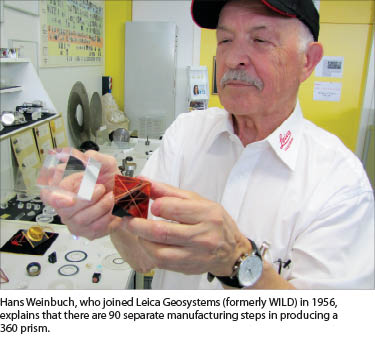
Weinbuch continued the tour through Swiss Optics, noting the discard piles of lenses and prisms that did not meet standard. He held up a 360 prism and said with a smile, “We hear complaints about how much this costs. Of course, [the customers] do not realize that there are 90 stations [manufacturing steps] in the production of [this].”
We were shown the specialty test stations for each type of glass component. “There are hundreds of types of glass,” said Weinbuch. “We apply special types of coatings that allow [for instance,] the surface of a prism to split beams, allowing one through and another to deflect to [another part of instruments].”
The tour through the partner machine shops (no photos allowed) was equally as eye-opening. Again, rigorous testing is performed before every part reaches the assembly floor, and that’s for every part—no sampling.
The Main Assembly Floor
“An assembly team member might spend several years in sub-assemblies,” said Gallus Schlachter, team leader for production engineering on the main assembly floor. “And then [several] more years on a ‘circular-table’ before moving on to adjustment or other jobs.”
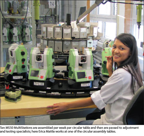
Erika Mattle, working on one of the circular tables for the past five years, began with a four-year apprenticeship at Swiss Optics. Each circular table moves 10 instruments through the final assembly stage. Mattle showed the instruction book for the MS50s she assembles—there is at least one page per component. Each screw, or group of screws, may require a specific torque wrench.
“Each instrument has to have exactly the same assembly standards,” said Schlachter, and, “that goes down to how much the screws are tightened. If some were over tightened more than others, [the instrument] might react different from another instrument on the same line. The goal is consistency.” Tightening too much on one side would introduce a bias or stress that would compromise the motion and alignment of the precision components, like the cameras, laser, and piezo drive.
 An apprentice on any step of assembly, adjustment, and testing must get various pages in his or her training guide signed off—“first aid, optical test instruments, tools, liquids and oils they use, cleaning solutions, operation of the circular assembly tables, adjusting their jigs,” said Schlachter. “Every trainee has this book, and the team leader can decide when someone’s been signed off on a particular item.”
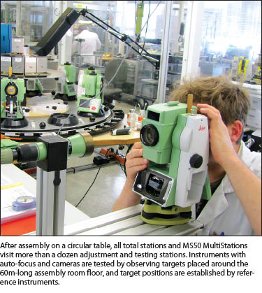
The next step after the circular table is a series of adjustment stations along what looks more like a traditional assembly line. For instance, there is a new type of autofocus for the MS50, and this is tested in the main assembly room with positions set with a reference instrument, and then they compare the EDM at different distances with what’s focused all around that room. These kinds of comparisons help it focus at any given distance. A resolution target is used to see if it is a clear image.
There are no motivational posters on the walls (no clutter at all), but there is one simple digital display at the end of the room showing the production target and progress. This is next to a display showing (to scale) the width of lines of resolution for various angular increments: 1” = 3cc = 0.000006rad = 5mm/1000m. There are test stations and targets set all over the 60m-long room for various components like the telescope camera and overview camera.
I asked Simon Calderara, director of production, TPS/GPS, if they took the assembly crews outside to have them operate a total station. He said that it “wasn’t really that necessary for assembly—much better to concentrate on the science and technology of the items they are assembling.” But, he added that, “perhaps once every couple of years they might have some sales staff take them outside to give them an overview—good for the mindset and to connect them with the product, but this is very serious team and they really concentrate on the tasks, subassemblies at hand, and testing.”
 Downstairs from the main assembly room, Calderara opened the climatic test chamber, a room where each instrument, depending on type, might be subjected to many hours of tests at temperatures ranging from -20ºC to +50ºC. Team members wear specialized suits, must take periodic breaks, and may receive hazard pay.
The Swiss Touch
Not only are Leica Geosystems’ standards being met during the subsequent testing, the calibration laboratories (SCS079) are accredited by the Swiss Accreditation Service (SAS)—you see numerous official certificates and logs throughout the testing rooms. Down on the lower floor (a stable and climatically controlled environment) are more inspection and testing facilities.
One particular large device is the TPM (Theodoliten Prüf-Maschine), a unique device they built themselves to meet federal standards that tests the collimation of the optics for the total stations. Schlachter explained, “This tests to one tenth of a second. We test the calibration over a whole night, and if it does not meet two tenths of a second we have to redo the whole calibration.”
Schlachter said that the specifications are over achieved. He said, “Many of the individual components are of a much higher precision than the whole.” He added, “The whole is definitely well within what is stated.” Calderara noted that while they do not wish to overstate capabilities, they are very confident that the instruments are more precise than stated.
The all-important EDM is tested on an automated track 120 (2x60m) long. Each driven prism is moved along the track, and every few centimeters multiple observations are made and compared to those from an interferometer. Schlachter showed me the results on a graph and said of the tolerances, “These are much less than one millimeter in 60m.”
The EDM in the MS50 also employs a fairly new technology. Hans-Martin Zogg, product manager TPS, explained Wave Form Digitizing (WFD): “This is new for total stations. The advantage with waveform digitizing is that you have very fast measurements so you can do scanning with up to 1,000 points per second, and you can have very long-range reflectorless observations with the Nova MS50 with up to 2,000m. Waveform digitizing technology is a specific type of a time-of-flight measurement system.”
Zogg continued, “The way it works is that it sends out a signal and detects and stores a digital signal vector. A small part of the signal is directly guided through an internal path during the measurement and serves as calibration measurement. If you were to view this on a graph, you would see the start pulse of the signal from the calibration path, and then you would see a stop pulse of the returned signal reflected from the object. If you do an accumulation of the received signals, you can afterwards digitize the start and stop signals and use them for the calculation of the distance you are observing.”
Some describe the culture of orderly manufacturing and precision at the Heerbrugg campus as being nearly an obsession. Weinbuch took me through a mini-museum there of Wild and Leica Geosystems instruments where I noticed no products with what might have been called “gimmicks.” Instead the museum is more of a timeline, a steady progression of well-known instruments, popular within the surveying profession—an enduring legacy and an on-going commitment to providing precision instruments and solutions.
Sidebar 1
What Is a Piezo Drive?
It makes for fast turns and low power consumption. Piezo drives are an interesting development that has been implemented for a few years by Leica Geosystems. Several small slivers of piezoelectric material flex when a charge is applied, and they “nudge” a plate much in the way an inchworm would shift its fore and aft, except this is done at dizzying speeds.
A piezo drive is designed for high speed, for precision, and for none of the friction and wear of legacy servos and gears. Plus, there is no power draw unless it’s activated. In fact, the drive starts/stops precisely as the current is switched. Another touted advantage is that it should be much more immune to magnetic interference than traditional motorized and magnetic drives.
Sidebar 2
Solid GNSS Box
In response to my question, “What’s cool?” about the manufacture of the GS14 GNSS rover, Bernhard Richter, business director GNSS, said, “You see it and you might think—just another box?” He adds, “Just pick it up, and you can feel the difference from [off-brand] boxes.”
Richter said, “There are eight sealing points for the battery compartment; most boxes have two. There are 18 screws holding the top on for well distributed pressure on the sealing ring and for optimum stress distribution in case of a drop. And this [a rectangular black protrusion on the bottom] is a compensation valve. In working at [for example,] minus 10ºC the air condenses, and moisture could be pulled in. The seals and valve [apply] constant pressure. [This] would work after one hour underwater.”
Richter added, “We test every unit in production for water tightness by [applying a] vacuum pump on each to put negative pressure on the valve, whereas others [may simply be] looking for bubbles in water.” He explained the multi-frequency nature of the unit—“the UHF band all the way from 400 to 470MHz, Bluetooth, and 3.75G cellular technology.”
Richter noted specific design considerations his team holds as crucial. “We think this is the smallest practical diameter for a high-performance, multi-frequency GNSS antenna. If [you try to] go smaller, you can run into phase center accuracy and multipath problems.”
As to their approach to the dynamic growth in constellations and GNSS modernization, “We do not want to lock down the receiver; we can replace modular boards as [GNSS] changes.”
Sidebar 3
Leica Jigsaw Jps
An intriguing mix of technologies culminated in the Leica Geosystems Jigsaw Positioning System (Jps). While the focus is mainly on mining markets, the product is a hybrid GNSS and terrestrial signal base positioning system that might hold promise for other positioning applications.
A Jps receiver contains a GNSS receiver and a Locata receiver. (Locata is the Australian company that has inspired a lot of interest in ground-based positioning.) Standalone Locata implementations are a connected network of ground transmitters that do ranging in the same way as GNSS and can work in completely GNSS-denied environments, even indoors as they synchronize signals from a short-range local network of transmitters.
Leica Jps, explained Frank Takac, chief engineer and head of R&D for GNSS position engineering, incorporates the available GNSS signals into the solution; this adds high elevation signals to improve the overall geometry of the ground network. Takac said the goal for Jigsaw is to “combine all of the positioning signals that we have, bundled together in an integrated solution.”
Takac explained the advantages by example: “For instance, you have an [open pit] mining situation where you do not have enough GNSS satellites in view for a solution, so with the combined GNSS and Locata solution you can still get a precise position. To achieve this integration, we estimate all of the unknowns between GNSS and the Locata system in a tightly coupled solution.” Mines using Leica Jps have recorded a signal availability increase from 70% (no Jps) to 87% on average.