Types of Distances for Geodetic Observations
This article explores the various types of distances that are often listed on GNSS adjustment reports; for related articles on the difference between geodetic and observed azimuths and angles, see “Where Theory Meets Practice” in Professional Surveyor’s March and May 2014, issues.
Slope (slant) distances (S) observed on the surface of the Earth are not easily reproducible due to the heights of the instrument and reflector, which are lost once a setup is taken down. This is also true for the horizontal distance at the instrument setup.
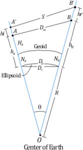
Figure 1
Theoretically it should be noted that the horizontal distance from A′B′ does not equal the horizontal distance B′A′. You can verify this by drawing perpendiculars from each point shown in Figure 1 to the opposite radius, and then measure the two horizontal line lengths which are perpendicular to the Earth’s radii.
From a practical point of view, these differences are not measurable with the typical distances observed in surveying, and thus this difference is ignored. In any event, GNSS adjustment reports typically list the distance between monuments, which is the mark-to-mark distance shown in Figure 1 as Dm; or a geodetic distance, which is Dg in Figure 1; or a grid distance (not shown), which is related to some map projection system such as state plane coordinates. (This topic is covered in the September, 2013 issue of Professional Surveyor).
The problem of reporting a distance between two monuments also exists with EDM calibration baseline reports where typically the lengths are listed as mark-to-mark distances. Thus, surveyors should know the differences in these reported lengths, and how to reduce the observed distances to mark-to-mark distances, geodetic distances, or grid distances. Since the reduction of observed distances to grid distances was covered in the previously cited article, this article looks at the reduction of an observed slant distance to it geodetic length and the mark-to-mark length.
REDUCTION OF OBSERVED DISTANCES
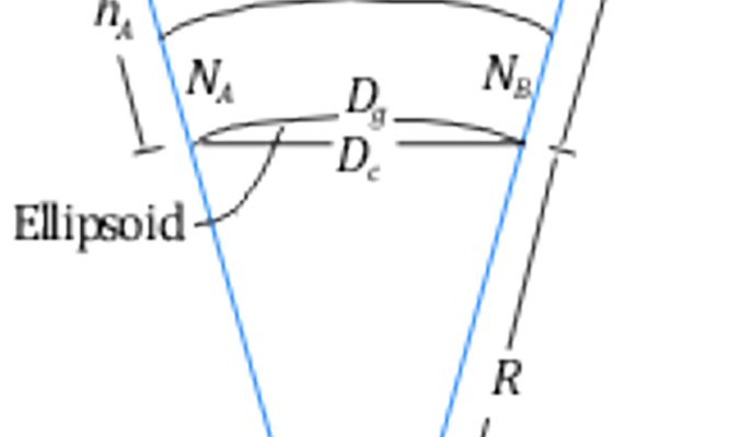
The reduction process is performed in several steps using simple geometric and trigonometric relationships. The first reduction takes the observed slope distance and reduces it to a chord length (Dc) at the ellipsoid. The second reduction determines the equivalent geodetic distance for the observation. Because the slope distance is observed at some location above the ground and the reflector is similarly off the ground, we need to add their heights to the overall reduction process. In Figure 1,
- hA is the geodetic height of the instrument at A, and hB the geodetic height at B;
- hi is the height of the instrument at A, and hr the height of the reflector at B;
- NA the geoidal separation at A, and NB the geoidal separation at B; and
- HA and HB are the orthometric heights (commonly referred to as elevations) at A and B, respectively.
The mark-to-mark distance (Dm) and the geodetic distance (Dg) are often reported in GNSS adjustment reports, although not all software manufacturers clearly label these lengths as such.
Because we need the radius of the Earth R and the geoid separation in this reduction, the example will be worked entirely in metric units. However, it can also be performed in English units, but recognize that all length units must be the same.
Suppose that the slope distance S is observed at A as 500.000 m. The elevation of A is 1300 ft (396.241 m) and at B is 1262 ft (384.658 m). The geoid separations at A and B were determined using the NGS toolkit software GEOID12A as −31.731 m and −31.685 m. The hi and hr are both set at 5.5 ft (1.676 m). What are the geodetic distance and mark-to-mark distances between A and B?
SLOPE DISTANCES OBSERVED
ON THE SURFACE OF THE
EARTH ARE NOT EASILY
REPRODUCIBLE DUE TO THE
HEIGHTS OF THE INSTRUMENT
AND REFLECTOR.
From Figure 1, we see that the geodetic heights of the instrument and reflector are h′A= 396.241+1.676 − 31.731 = 366.186 m and h′B = 384.658 + 1.676 − 31.685 = 354.649 m, respectively, which means the difference in geodetic height of the instrument and reflector is 11.537 m. Using an average radius of the Earth of 6,371,000 m, the chord length Dc is computed as shown in Equation [1].
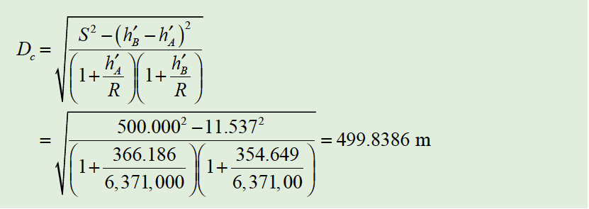
Equation 1
Using the relationship of a chord length on a curve, the geodetic distance Dg is as shown in Equation [2]. Note this last reduction assumes that the Earth is a sphere, which we know it is not. However, for the short lengths that are observed typically in practice, this assumption is valid.
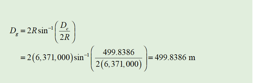
Equation 2
Finally, the mark-to-mark distance Dm is computed as shown in Equation [3] where hA and hB are the geodetic heights of stations A and B, respectively. That is, hA = 364.510 m (396.241 – 31.731) and hB = 354.649 m (384.658 – 31.685). This is the length between the monuments on the ground. From this computation you can see that the effect of the height of the instrument and reflector on the slant distance is minimal at a 0.1 mm.
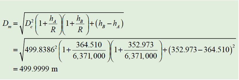
Equation 3
However, we can see that the geodetic distance is 0.1614 m or 0.53 ft different from the observed value. This is considerably different from the measured value. GNSS software will report the geodetic length of 499.839 m and/or the mark-to-mark distance between the monuments of 500.000 m. However, it will not provide the horizontal distance as measured by the instrument at the height of the instrument.
Note that the radius in the azimuth of the line should be used to reduce these observations. The radius in the azimuth is given by Equation [4] where α is the azimuth of the line from the observing station, M the radius of the ellipse along the meridian at the point, and N the radius of the ellipse in the eastwest direction at the point, which is known as the normal.
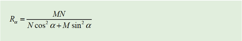
Equation 4
The radius in the meridian, M, and radius in the normal, N, are computed as in Equation [5] where a is the length of the semimajor axis of the ellipse, e the eccentricity of the ellipse, and φ the latitude of the observing station. However, the difference in using an average radius of the Earth and the radius in the azimuth of the line is typically minimal for the short lines that are observed in surveying typically.
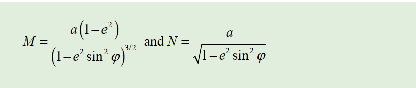
Equation 5
Now let’s assume that this is a GNSS baseline vector with a length of 5000 m. Using the same values for the other parameters, we have that the geodetic distance is 4999.7040 m, or it differs from the slant distance by 0.296 m or 0.97 ft. The mark-to-mark distance is 4999.9987 m, which differs from the slant distance by only 1.3 mm, or 0.004 ft. As can be seen, the mark-to-mark distance is very close to the observed slant length. Even if the station differed in elevation by several hundred meters, the slant length and mark-to-mark length are very close.
It is incumbent upon the surveyor to recognize the difference between what is shown in a GNSS adjustment report and what is measured by a total station, as well as the differences between distance observed with an EDM and those listed in a GNSS adjustment report, which are either geodetic, mark-to-mark, or grid. Anyone using GNSS software should be able to convert between those listed in the adjustment report and observed by a total station.
Formal education provides the surveyor with the background necessary to become a competent professional. It is time that all surveyors take a serious look at the direction of the profession technologically and the need for a baccalaureate degree to become a future professional.