The third and final installment of a look at the inner workings of high-precision surveying rovers.
In parts one and two, which appeared in the two previous issues, we focused on antennas, amplification, housing, channels, boards, and gates. This installment continues with signal matching, positioning engines, and additional components.
Matching Signals
To distill the observed signals into something that positioning engines can utilize, the ASIC must match many signal structures. “There is an interface control document (ICD) published by constellation provider, like the U.S. government that defines a signal in space,” said Dr. Stuart Riley, vice president of technology/GNSS at Trimble. “That is enough information for somebody who’s skilled in the art of GNSS, to be able to design the receiver and, and because of code-division multiple access (CDMA), the first phase of receiving a signal is to generate a precise replica of that code.”
For example, the GPS C/A code, which is the most widely utilized GNSS signal today, includes a short spreading code that repeats every millisecond and lower rate navigation data rate. Then you try and synchronize by matching up the local replica with the one that’s been transmitted.
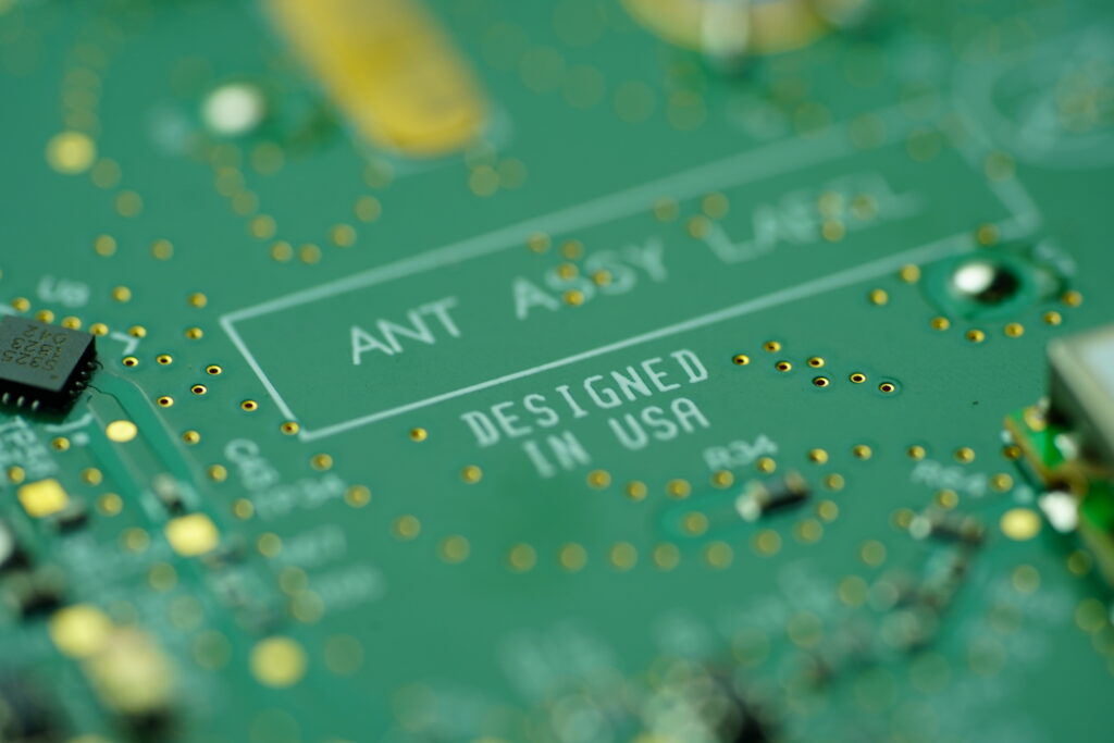
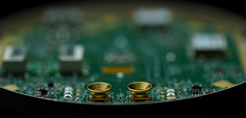
Part of the antenna assembly of the Trimble R12i – Image credit: Michael Dix, Trimble
“A further step is to generate a carrier replica of the received signal, which also provides the carrier observable,” said Riley. “You have to generate a replica of code that’s generated by this. It’s the same for all of these signals. The Galileo ICD defines the Galileo codes, and you just make a local replica of that, and you have to time and frequency align it in what we call a correlation operation. And at that point, once you get maximum correlation, maximum similarity, then you’ve got optimal lock and your measurements flow.
ASIC design has had to rapidly evolve in recent years to be able to accommodate all the new satellites and signals, as has the processing power for the positioning engines, to be able to do the many more things being asked of receivers. Several manufacturers have introduced new models that can handle this increased load, far greater than rovers of only a few years ago. There are older receivers that can “track” multiple constellations, however, they may not be powerful enough to fully utilize every new signal, some signals of which were only introduced within the past five years.
Engines
“Think of the ASIC as hardware acceleration for signal tracking or correlation operations,” said Riley. “Essentially, they aid in the decoding or tracking of the satellite, then everything else is in software. So, from the ASIC, we get measurements. They’re not in the international system of units. They’re not in meters. They’re just sort of hardware words. We have scaling that we have to apply.”
It’s a measurement layer that’s in software that takes different things from both the software and the hardware, combines it together and gets measurements to cycles, or meters, or whatever units are desired.
Then in the software layer beneath, in processors on the board, you have the measurement engines, sometimes called processing engines, navigation, or positioning engines. With the refined products of the ASIC, these engines do the magic of multilateration. This is where steps like fixing pseudo-range ambiguities happens, where code, clock, and orbit biases are applied, where differential, RTK, and PPP approaches are activated.
The reality of taking in so many signals from so many satellites, and (depending on approach) putting them under one giant filter to process together, takes a lot of horsepower. Also, consider that the engines are computing positions at a high rate ( bit.ly/RTK-Rate). For instance, in nearly all RTK rovers the default is five or 10 times per second (5Hz – 10 Hz, even with a base output of one second, or 1Hz). Certain specialized applications can solve at even higher rates. Newer rovers need to be far more powerful. Again, this can be a challenge for very-low-cost systems.
Components and complete rovers undergo extensive testing. In addition to outdoor testing, anechoic chambers are used, where individual variables can be controlled. These include simulated signals, interference, multipath, and even playbacks of observations recorded in different environments around the world. Image credit: NovAtel
A whole separate treatise would be needed to cover all of the varied approaches to positioning solutions. Leica Geosystems calls their engine approach “Self-Learning” referring to the way it considers which signals and satellites to include.
Trimble called one of its approaches HDGNSS. Tersus calls its latest engine approach “Extreme RTK.” There are many others.
Manufacturers continue to improve and update positioning engines. There may be many varied approaches, but when considering the current state of GNSS, advances in the underlying science, and advances in hardware and algorithms, the results tend to be very good all-around (caveats about very-low-cost systems noted).
Not to go too far down the rabbit hole of approaches for positioning engines, but a few aspects could be mentioned. No doubt you’ve heard about Kalman filters, a mathematical rather than a physical filter, employed in most rovers.
“Generally, factor graph optimization (FGO) based algorithms exhibit better accuracy and robustness, and extended Kalman filter (EKF) based algorithms have higher computational efficiency,” said Cheng Chi, senior algorithm engineer with Tersus GNSS. “Theoretically, there are two main advantages of the FGO-based algorithms over the EKF-based algorithms.
“First, FGO iterates several times to get a reliable estimation under the strong nonlinearity, and EKF mostly does this only once. The iteration leads to comparably high precision for estimated states in each step. The high precision state will act as a decent linearization point and benefits the following epochs.
“Second, FGO maintains a batch of measurements and states, while EKF may only take one epoch into consideration. This batch processing enables adjusting the states in a wide span, and thus gets optimized estimation results by taking better advantage of the correlation between states.”
Chi explained where FGO might be preferred: “Since the FGO-based algorithms need to maintain a batch of state, the dimensions of the solvers are relatively higher, causing a comparably larger computational load, which is a disadvantage over EKF.
Therefore, the EKF-based algorithms are commonly used in cost-sensitive (limited computing capability) or real-time-sensitive (needs fast processing) products, while FGO-based algorithms are commonly used in corresponding non-sensitive products where improved accuracy and robustness are also required.”
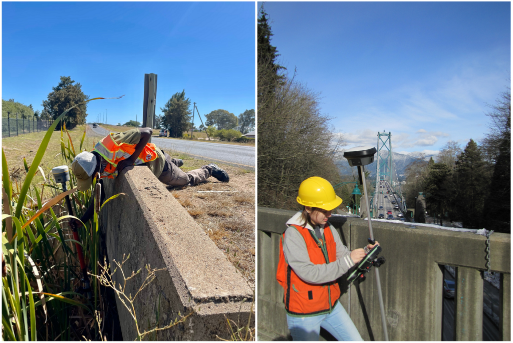
No-calibration tilt compensation has become a standard feature on most new rovers, adding IMU and modified antennas to designs – Image sources: Lee Landman (left), G. Schrock (right)
In general, just about any rover you pick up is doing EKF, however, FGO is being leverage in some approaches for processing GNSS and IMU together, for instance, for some no-calibration tilt compensation solutions.
Be it autonomous, DGPS, RTK, network RTK (NRTK/RTN), PPP, or hybrids, the components of the receiver are designed to distill the raw observations into something the positioning engines can use. The rover must also take into account the clock, orbit, and reference frame differences and biases of each constellation.
Once you have a position, the job of the receiver is pretty much complete. The engines do not “think” in terms of datums, units, or coordinates that you use on a day-to-day basis. Projections and transformations are handled in the field software.
The same with corrections. One misconception about real-time networks is that they are broadcasting “state plane coordinates.” No, they are just sending observation state representation (OSR) “corrections.” Broadcast precise point positioning (PPP) simply provides state space representations (SSR) of clock, orbit, ionospheric model data, etc. The rover applies the corrections and gives you a position, but everything else happens in your field software.
Additional Components
For communications between the rover and sources of corrections, a rover can pack a UHF or spread spectrum radio internally (or externally), and/or modem (for IP or NTRIP sourced corrections). Often though, users will use the modem built into their data controller or tablet, or Wi-Fi to a portable or phone hotspot. One disadvantage of built-in modems is that they can eventually become obsolete (as happened with the sunset of 3G).
Long gone are the days of connecting the rover “head” to the data controller via cables. Most controllers/tablets connect via Bluetooth, so you will find Bluetooth as a standard component of nearly all newer rovers.
Most new rovers have no-calibration tilt compensation, almost a standard in the industry. Internal components to enable this can include IMU, electronic gyros, and accelerometers. We’ve even seen a tilt compensated rover that has downward facing laser to be able to skip measure-ups.
While there was a wave of magnetically oriented tilt compensation systems over a decade ago, those were problematic, and surveyors typically would not use them. The new wave of IMU and trajectory-oriented no-calibration tilt systems, introduced only five years ago, are getting a much better reception, and have become standard on nearly all new (upper tier) rovers (bit.ly/Rover-Tilt).
Cameras are appearing on rovers, for photogrammetrically computing offset points from images. One common approach is to carry the rover parallel to the objects desired, with the camera facing the points of interest, and it will take a series of images as you move. Afterward, in the field software, you pick a point you wish to measure in multiple images.
Another variation is picking a point from the live view of the camera, then walking the rover across the scene. It will automatically identify the same point in subsequent images, until it has enough to compute the position of the point. We’re even seeing rovers with two cameras—one for photogrammetry and another pointing downward for stakeout.
What could be next in rover components? Solid-state lidar is a likely candidate, not just to do limited “scans” but to assist in point stabilization in the way that mobile mapping systems leverage live SLAM data. For that matter, a SLAM scanner could possibly be added.
Those musings aside, rovers continue to evolve. However, the present state of rover technology (and performance), through parallel R&D is rather astounding, and fairly ubiquitous (across the high-end classes of many brands and models). It is difficult to look at a rover and datasheet and conclude that it would have some magical advantage over a different one. Field testing is the only way to determine that.
This exercise in looking under the hood of a typical survey rover was (for me) very educational. However, in many ways, that unit on top of the pole is still doing a lot of magic that only GNSS engineers and scientists fully understand. That’s fine, they can keep developing amazing gear, and we’ll put it through its paces in the field, let them know what works, what doesn’t, and what we’d like to see in the future.
Click Here for Part One
Click Here for Part Two