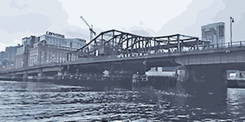
Nautical lidar works for a waterway bridge replacement project in Boston.
Waterway projects can pose major challenges for surveyors and engineers needing survey-grade data because of unpredictable variables in the marine environment. Surveyors face inaccessible areas, tidal changes, marine traffic, and unpredictable weather, as a few examples.
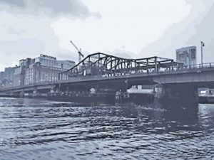
The Massachusets department of transportation (MassDOT) undertook an estimated $100,000,000 bridge replacement on a Boston waterway project wherein they had to identify scouring, overhead channel clearances, and under-deck bridge conditions. They used 3D lidar as their prime tool, specifically, mobile lidar mounted on a boat by Terrametrix, a mobile mapping company based in Omaha, Nebraska.
Boat Attachment
“Mobile scanning from a boat is much the same as mobile scanning from a vehicle, with three important differences,” explains Terrametrix president, Michael R. Frecks, PLS.
“The first difference is how one attaches the mobile lidar scan system to the boat. When using a vehicle on a land-based project, there is the roof rack that can be utilized to attach the portable scan system to. Obviously, on a boat that does not exist.”
Every project is a new opportunity for creating a mounting platform that must be simple and must leave the boat in the same condition as before, and of course it must be secure.
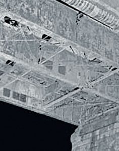
One-pass lidar collection obtained from the vessel shows the underneath of the bridge. This data is as detailed as bridge collections on highways, although the elevation will vary with underneath marine data due to the rise and fall of the water level.
Frecks further explains, “A mounting platform must be designed, built, and installed on the boat, and since we travel to all corners of the Earth we never have the same model, let alone the same boat. The logistics of obtaining material and tools to build the mounting platform is also something that takes planning and ingenuity.”
According to Terrametrix scan technician, Todd Gnuse, the challenges are more than logis- tical attachment. “Mounting the system to the boat to stabilize the IMU—so as not to have any deviation between the lever arm measurements and laser—was my biggest concern.”
For this coastal project, Terrametrix was able to use their existing mounts for both the IMU and the laser so the lever arm measurements would stay constant. And they installed the mobile lidar system directly from their truck to the boat in less than an hour.
The versatility of their custom swivel mount for the scanners and GPS receivers enabled the system to be mounted on the back of the boat set straight back and mounted high enough—so as to avoid interference from the boat—for seamless data collection of water surface and the above areas.
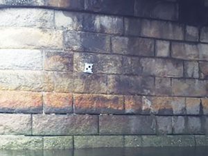
Control targets for nautical capture are placed like static lidar capture on the sides of structurally sound piers.
A second antenna was added to the front of the boat, addressing concerns of accuracy between the IMU and GPS measurements as they corresponded with the swaying and the boat’s quick movements, or yaw, pitch and roll.
“The IMU takes into account the yaw, pitch, roll, and acceleration of the boat due to waves much the same as it does on a bumpy road. Although the waves are usually much more severe than bumps on a roadway, a high-precision IMU measuring at 400 Hz can handle the movement with no issues,” explained Frecks. “Just don’t try this with a less-expensive IMU.”
Initialization
On land, initialization is very straight forward depending on the scan system used. Some mobile scan systems require a static initialization, some up to 10 minutes. Obviously, that is not possible while sitting in the water.
The scan system MassDOT chose uses a moving initialization. “We have found a moving initialization to be beneficial, even on land, where safety and traffic concerns require stationary initialization sitting on the side of the road,” said Frecks.
“But, it was not without its unique challenges. The mobile system requires movement at 45 mph or more to initialize over a few-minute period. Proprietary system software allows us to initialize at much slower speeds.”
Additionally, aiding in processing the IMU and GPS data, multiple passes were made under the bridge in different directions to verify the accuracy of the passes to each other and the control targets.
Ground Truth Checks
The third difference, according to Frecks, is targeting for ground truth (accuracy) checks.
“On land, a series of chevrons (or +) are painted along the driving route on a horizontal plane surface. On the water you must use targets that are placed on a vertical plane surface and in a location that can be surveyed to establish the x, y, z coordinates.”
Targets were placed on the vertical walls of the piers and abutments to add control to the scans. However, areas around bridge piers are challenging because the pier may be farther from the shore, exceeding standard operating conditions for a total station and GPS static observations. The difficulty is due to satellite-window issues with the bridge deck.
“During the project, we scanned between each pier going through each opening—twice—as we scanned from north to south, doing the two outside openings first as the tide went out rather quickly,” said Gnuse.
“The tide was going in or out as we scanned the underneath of the bridge, and there were differences in water levels from start to finish. From the time we took off from the dock until we returned, the tide had dropped over six feet.”
After processing the trajectory, the IMU and GPS data were accurately mapped, and the drop in tide vertical positions was measured.
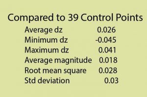
“With the second GPS antenna and IMU measurements combined, the trajectory error was reduced to less than 0.08 feet between passes. The overall RMS error was 0.03 feet after aligning all the flight lines.”
The project was completed in two hours.
The goal of this project was to collect all the structural elements of the bridge such as girders, piers, and cross members and the location of the utility lines under the bridge deck, as well as to provide an historical documentation of the century-old bridge.
Other project uses for a water-vessel-mounted mobile lidar systems are deformation for erosion, coastal monitoring, asset inventory (including brush areas), and overhead clearances of bridges and catenaries.
Because lidar is line of sight, there are many areas that cannot be captured from the shore.
To read more articles from this print issue of xyHT magazine, click on the cover below.