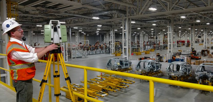
Above: Darling 3D scanning division manager Charlie Warren checks his settings while scanning the Mercedes-Benz U.S. International automotive plant.
A whopping 1.5-million square feet of a Mercedes-Benz facility expansion was scanned for as-built documentation and construction verification.
A GROWING geospatial application of 3D digital data from laser scanners is for as-built documentation and construction verification. By performing such documentation quickly—during construction or immediately after—contractors can verify that facilities are being built to match design. This makes installation and operation of prefabricated modules and plant equipment far more efficient as well as facilitating smart building apps and the internet of things (IoT).
Arizona-based Darling Geomatics has been doing this kind of work since 2002. In early 2018, the firm accomplished a potentially groundbreaking milestone that combines as-builts and verification using scanning.
“We were asked to verify that the 1.5 million square feet of expansion at the Mercedes-Benz U.S. international automotive plant in Vance, Alabama, met construction specifications,” explains CEO Mary Darling.
“This was shortly after building construction was completed, but before most of the manufacturing equipment had been moved in. Documenting the actual placement of new construction was a way to accelerate project turnaround, reduce rework during equipment installation, and of course provide a 3D record for ongoing maintenance and operations.”
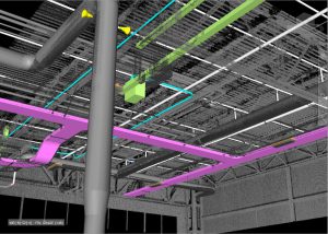
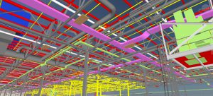
The as-built data collected with 3D laser scanning was compared to the Navisworks design model provided by the general contractor for construction verification.
Billions of Data Points in Eight Days
The project was ideal for 3D laser scanning, but it also presented challenges.
“In this case, we were working for the general contractor,” says Darling 3D scanning division manager Charlie Warren. “Mercedes-Benz is pretty particular with their specifications, and they felt a scan was the best way to verify that all their work was according to design. That part is standard for us, and we let them know that we work to a tolerance of six millimeters.
“What made this project different was the sheer size—1.5 million square feet is a lot of space, especially with all the ductwork and conduits being installed. And some equipment, including robots, had already been moved in. So mainly this was a big project, with some complications, and a relatively short window to get the work done on site.” To prepare, Warren looked over the drawings and devised a plan that took advantage of the layout.
“The expanded facilities were on a grid and featured a large number of manufacturing bays,” he says. “So it was relatively easy to plan our scan setups and sequences to avoid excessive overlap.”
He also arranged for three scanners to be at the Mercedes-Benz plant for the entire eight-day time window. All were made by Leica Geosystems, which was important to Darling because, “these scanners bring excellent data quality and accuracies < inch (6mm), while also being highly portable and quick to set up.”
Data consistency was also important. “Using all Leica Geosystems scanners is a good way to keep our data consistent, especially since we use Leica Cyclone software for processing,” Warren explains. “For this project, we used our own C10 and P20 scanners and brought in another specialist with a P30. All of them had the range and accuracy we needed here, and they all worked together well.”
The scanners did have different specialties. “For tighter spaces we used the P20—it’s just so fast. And the C10 was a better choice for the longer shots we used to get onto the local survey coordinate system. But really, all three scanners were up to the task, and we gathered billions of accurate points that all registered precisely.”
One trick that helped the three-man/one-woman crew move quickly was wheeled tripods, which worked well on the plant’s smooth concrete floors.
Saving time was important; in just eight days, the team scanned billions of points from 920 setups, including shots to interior and exterior control points to keep the scan data on the same basis as construction. All the data collected was good, and it all registered easily into the software needed for comparison to the Navisworks design model provided by the general contractor.
Without 3D scanning and construction verification software tools, spot checks at various locations throughout the manufacturing plant would have taken considerably more time, provided only a fraction of the detail, and introduced the risk of human error.
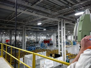
The Darling Geomatics team collected billions of accurate data points that all registered precisely.
Verification through Comparison
With all the spatial data recorded on the construction coordinate network and processed and registered, Darling Geomatics now had as-built data that could be compared to the Navisworks model and could move on to actual construction verification. This process was accomplished by comparing the scanning point clouds to the design and fabrication models.
The news was good. Darling’s work was able to prove that all major construction components—steel, concrete, ducting, etc.—were exactly in place (within a 1/2 inch), and that even less-consequential elements, like lighting, were within 2 inches of design.
It seems like a lot of work just to confirm that new construction is where it’s supposed to be. But it wasn’t a lot of work—just four people and three scanners for eight days and several weeks of office time. That’s a minor line item on a project of this size, and even that cost was more than covered by the greater confidence and efficiency made possible when designing and installing the actual automobile manufacturing equipment.
Put simply, using digital data composed of billions of accurately scanned points to perform high-level quality control was an investment that paid off for all stakeholders.
_________________________________________________________
Design and Change Detection with 3D Data
Over the last 15 years, digital data has become an integral part of engineering and architectural workflows. Many of Darling Geomatics’ clients use 3D scan data during the design phase of facility upgrades.
For example, one of Darling’s clients did not have current as-built drawings when they got ready to design upgrades to their ammonia processing plant. The alternative to 3D scanning would have been for them to try to hand-measure all pertinent areas of the plant. The manual process would have been dangerous as well as prohibitively time-consuming and expensive.
Darling was able to scan the project in one and a half days and provide a detailed, accurate 3D model of the facility the engineers could immediately use to plan their upgrades with confidence.
Another use for 3D scan data is change detection. A copper mine client of Darling’s was concerned that the wall of a large storage tank had weakened and was beginning to shift or buckle. They asked Darling to monitor the wall for any movement. An initial baseline scan was performed, and then several months later a second scan of the wall was done.
A comparison of the two datasets showed specific areas along the wall where slight movement was occurring. Darling will continue to scan the wall every few months to show the rate of movement over time.
This change-detection process can be applied to topography as well. A client Darling has been working with for several years needs to monitor the changes to dry washes after the monsoon rains have come through to comply with their federal water permit. Over the years, Darling has been able to document the subtle changes.
This pre-project geomorphology and pebble-count information, acquired with laser scanners, will be used as baseline data to determine changes in the stream channel substrate during and after project construction.
On average, the digital data acquired with 3D laser scanning saves four to six times the cost of the service by streamlining projects and eliminating rework and change orders. The data also enables the smart building apps, IoT processes, and AI advances that are driving manufacturing plants into the future.
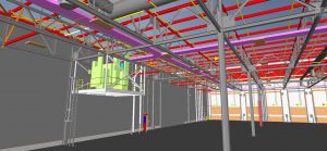
3D laser scanning provides a detailed, accurate 3D model that engineers can immediately use to plan upgrades.
For more information, visit https://darlingltd.com/ or http://3dplant.leica-geosystems.us/.
All images courtesy of Darling Geomatics.