Whether you learn fundamentals of surveying from a formal degree program, certificate program, CEU seminars and workshops, self-study, or in-the-field training, you feel a certain delight in that moment of discovery when the theoretical has met the practical. These moments come when (what first appear to be) dry mathematical or legal principles taught in the classroom reveal their real-world utility in the field or when the surveyor who has come into the profession via hands-on experience finds validation of established field practices in the pages of a textbook.
Where Theory Meets Practice kicks off with an installment by Dr. Charles Ghilani, surveying educator and author of surveying textbooks. This column will appear regularly with more from Dr. Ghilani and other noteworthy surveying and geodesy educators and practitioners. Each column will focus on a specific element of surveying or geodesy theory as well as practical applications. We hope you find these columns educational and will perhaps even pause for reflection on how we have gained our own understanding of these elements. We also invite your ideas for future installments of this new column.
At times there is a need to run a traverse between two state plane coordinate system (SPCS) zones. An example is a traverse that starts with Pennsylvania (PA) North Zone coordinates but connects to a station in the PA South, NJ, NY, or OH state plane coordinate system zone. There is often confusion on how to do this properly when it’s really a simple matter. To understand why this is the case, we need to understand the theory behind map projections.
 Map projections provide a 1-to-1 mathematical relationship between points on the ellipsoid having geodetic coordinates with those on the map projection surface, which is also called a developable surface, having map or grid coordinates. State plane coordinate systems use either a cone or a cylinder for their developable surfaces. For example, the Lambert conformal conic map projection system is used for the two state plane coordinate system zones in Pennsylvania.
Some people believe that the zones stop at their limits. This is equivalent to people believing they would sail off the edge of the Earth before Columbus proved otherwise. While these developable surfaces have their limitations, it is important to realize that the map projections themselves span almost the entire Earth, and thus do not have the physical boundaries as defined by the state plane coordinate systems. In essence, the SPCS zone limits are not defined by the map projection system but rather by the desire to limit the scaling differences between geodetic distances and their equivalent grid distances on the mapping surface.
The fact that the map projection surface does not stop at some political boundary becomes the basis for converting between zones. For example, the PA North zone actually circles the Earth. So what happens if you use the PA North zone parameters to compute a point in Europe? Quite simply, you would get rather large SPCS coordinate values and a huge convergence angle. Still, if proper reduction techniques are followed, the computed coordinates will be located correctly in the map projection system. Figure 1 depicts the entire conterminous U.S. (CONUS) projected using the PA North zone state plane coordinate system.
Notice that the PA North zone projection system does not stop at its well-known political boundaries. Thus, it would be entirely possible for the United States to adopt the PA North zone map projection system for the entire country. However, if we did this the distortion between the geodetic distances and their equivalent mapping lengths would be considerable in most regions of the country, and the difference between a geodetic azimuth and its equivalent mapping or grid azimuth could be large. For example, near the west coast it would be on the order of 27°.
Nevertheless, this example demonstrates one possible solution to traverses that cross zone boundaries.
Conversion Procedure
Recalling that geodetic coordinates for a point are only datum-specific and that there is a mathematical 1-to-1 relationship between map projection coordinates and their equivalent geodetic coordinate values provides us with a zone-conversion procedure. First, compute geodetic values for any control having SPCS coordinates or azimuths in the second zone, and then convert these values into their equivalent SPCS values in the primary computational zone. The traverse can now be computed and adjusted in the primary zone as if it never crossed into another zone. Following this, the adjusted coordinates for the stations located physically in the second zone can be converted to their geodetic coordinate values and then back to their equivalent mapping values in the second zone if required.
Itemizing, the procedure is:
- Convert all control, coordinates, and directions from the second zone to their geodetic equivalents and then to their equivalent SPCS values in the primary zone.
- Reduce the observed distances to their grid distance equivalents in the primary zone.
- Determine the adjusted coordinates for all stations in the survey using the primary zone. For example, if a survey started in the PA North zone and crossed into the NJ state plane coordinate system, compute the entire survey’s coordinates in the PA North zone system using PA North zone values.
- If required, perform inverse SPCS computations on all points that need to have coordinate values in the second zone. This will derive their equivalent geodetic coordinate values. In this instance, convert all PA North zone coordinates for points located physically in New Jersey to geodetic coordinates of latitude and longitude.
- Finally, using the geodetic coordinates of the stations determined in step four, compute their state plane coordinate values in the second zone. In this example, compute the NJ SPCS coordinates from their geodetic coordinates.
You have now determined SPCS coordinates in another system from the original survey. Steps four and five are required only if the coordinates of the stations located physically in the second zone are required to have the coordinates in the second, or if adjusted observational values are required for the distances or directions of the courses in the second zone.
If all the steps are followed properly, there will be no loss of accuracy to the survey. If you adjusted your original survey, the stations in the second zone will also be adjusted, and their inverses will provide adjusted distances and directions in the second zone’s SPCS system.
A second method that could be used is to:
- Determine the geodetic coordinates between two consecutive traverse stations that are in the overlap region between the two state plane coordinate systems. Note that two consecutive traverse stations are required in order to transfer the azimuth of a traverse course from one zone to another.
- Using these geodetic values of the coordinates and azimuths, compute their SPCS coordinate values in the second zone.
- Using these values, continue your survey in the second state plane coordinate system.
However, this method inhibits one’s ability to perform standard traverse adjustments on the survey. Thus, I prefer the first method because standard computational practices can be used. If required, after adjusting the survey, the final adjusted station coordinates located physically in the second zone can be transformed back to the original zone, and from these coordinates adjusted observational values appropriate for the second zone can be computed by inversing the SPCS coordinates.
The first method has one important concept that must be followed. That is, all observational reductions and coordinate values must made be in a single zone. This is due to the fact that not only are the coordinates in the two zones different but also the convergence angles for the direction of courses and the scale factors at the stations, which are used to reduce geodetic distances to their equivalent mapping lengths.
For example, if the survey is performed in the PA north zone but the closing coordinates are in the NJ state plane coordinate system, the coordinates of the closing station(s) will need to be converted to their equivalent PA North zone values. Additionally, the closing azimuth for the traverse in NJ would have to be converted to its equivalent PA North zone value, and the horizontal distances would have to be reduced using PA north zone scale factors.
In essence, all observations and control values must be in a single SPCS zone before any standard traverse computations are performed in step three. After the coordinates are adjusted in the primary zone, the adjusted coordinate values can be converted back to the second zone using steps four and five, and from these values the adjusted observational values derived.
If all the appropriate reductions are made on the observations, the quality of the final coordinate values will match that of the survey or the control. Because many surveying software packages can convert coordinates between geodetic and state plane coordinate system zones, the process is really quite simple. Simply perform all reductions and computations in one zone and then convert the final adjusted coordinates of the stations located physically in the second zone to their equivalent values in the second zone. If adjusted directions and distances are required in the second zone, these can be determined from the second zone’s adjusted SPCS coordinate values.
An Example
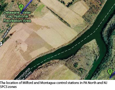
As shown in Figure 2, the NGS control stations of Milford and Montague are extremely close but in two different SPCS zones. Milford is in the Pennsylvania (PA) North zone, which is zone 3701, while Montague is in the New Jersey (NJ) state plane coordinate system zone, which is zone 2900. The surveyor connects these two stations with a traverse. Now the surveyor must adjust the traverse observations to achieve geometric closures. At the end of the project, the surveyor needs to supply the two state DOTs with SPCS coordinates that are appropriate for their location.
The PA North Zone northing-easting (ne) coordinates in meters from the National Geodetic Survey (NGS) data sheet for Milford are (129832.919, 845336.070). The NJ ne coordinates in meters for Montague are (273222.895, 123964.515). The closing grid azimuth at Montague in the NJ SPCS zone is 155°14´43.3˝.
Using the SPCS83 conversion software from the NGS Geodetic Tool kit (www.ngs.noaa.gov/TOOLS/spc.html), the surveyor determines the geodetic latitude and longitude of Montague to be 41°17´37.79381˝N and 74°48´39.10902˝W, respectively with a convergence angle of −0°12´18.53˝.
Using the geodetic coordinates of Montague and the geodetic tool kit software, the surveyor now computes the equivalent PA North zone coordinates for Montague, which are determined to be (129352.324, 846126.042) with a convergence angle of 1°56´39.68˝.
Because the computations are to be performed in the PA North zone, the closing grid azimuth in NJ must also be converted to the PA North Zone. The equation to convert azimuths is
Azgeodetic = Azgrid + γ (1)
where γ is the convergence angle in the NJ SPCS zone of −0°12´18.53˝,
Azgeodetic the geodetic azimuth, and Azgrid the grid azimuth of 155°14´43.3˝. Thus the closing geodetic azimuth is 155°02´24.8˝, which is computed as 155°14´43.3˝ − 0°12´18.53˝. Using a rearranged Equation (1), this geodetic azimuth is now converted to its equivalent PA North zone value with the PA North zone convergence angle of 1°56´39.68˝as
AzPA North = 155°02´24.8˝ − 1°56´39.68˝ = 153°05´45.1˝
The surveyor now has the closing coordinates of the New Jersey control station and the closing azimuth in the PA North zone and can proceed to compute the entire traverse as if the entire traverse were in the PA North zone, which it is, theoretically.
Remember that all the distances must be reduced to their equivalent map projection lengths. Readers who are unfamiliar with reducing observed horizontal distances to their equivalent map projection lengths should refer to the references in the online version of this article.
Once the computations are complete and accepted, the coordinates of the stations in NJ can be converted from PA North Zone ne values to their equivalent geodetic coordinates using the same software from the NGS geodetic tool kit. Finally, using the geodetic tool kit software again, the surveyor can now convert the geodetic coordinates of the stations in New Jersey into their appropriate New Jersey state plane coordinate values.
For this entire procedure the only thing you must remember is that all observations and coordinates must be in the one map projection system before any traverse computations are attempted.