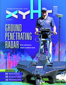
Arrays of multiple sensors and advances in processing breathe new life into the field of ground penetrating radar.
We continue to struggle with the opaque elements of our world. To be able to penetrate the opaqueness of night, fog, clouds, and the ocean’s depths is a relative snap compared to the challenges of seeing downward into terra firma. Civil engineering, utility engineering, resource exploration, archaeology, forensics all seek to define what lies beneath, by many technological means. Yet the only sure-fire answer comes from potholing: digging a hole. Maybe this is not such a hard rule anymore.
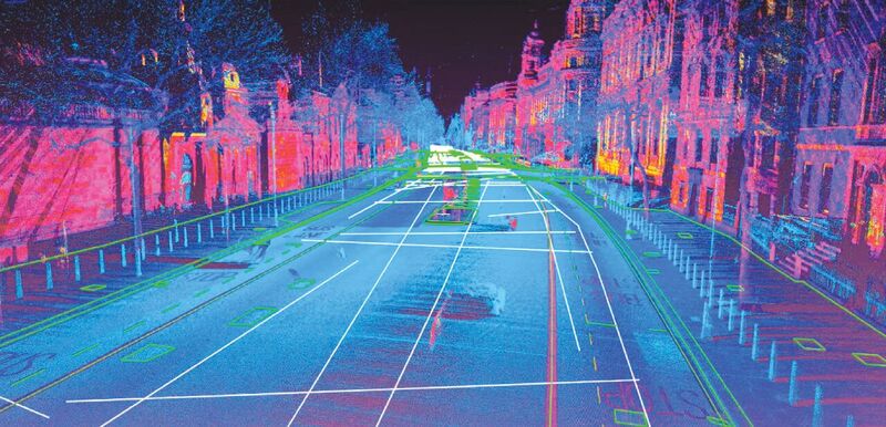
Above: A demonstration scan of a London street; mobile lidar for above ground and GPR for below ground. Credit: Leica Geosystems (part of Hexagon).
Ground penetrating radar has been used since the late 1920s, beginning not long after the first patents for radar. While GPR has truly been commercially available since the 1980s, its growth in use has been steady. But the sad reality is that, while many people who have tried GPR in past decades have been impressed, just as many may have been disappointed. Such disappointment might stem from a combination of unrealistic expectations; misunderstanding of the underlying science; or a belief that legacy solutions are hard to interpret, requiring specialized skills.
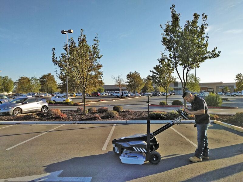
The STREAM C, a multi-array with 34 sensors and real-time pipe detection and mapping. Credit: BTL.
It was inevitable that a technology as promising as GPR would improve; numerous advances have been developed by multiple parties. I stand among those previously disappointed by GPR, but no more. The latest wave of solutions is impressive. For those who have deeply adopted GPR, much of the following may not come as a surprise, but we hope more of the previously disappointed might give GPR a second look.
Legacy GPR
The principle is quite simple, as the word “radar” in the term im- plies. Emitted signals bounce off obstructions or changes in the electromagnetic properties of objects or strata below. GPR operates typically in microwave bands, from 10MHz to 2GHz. There are signal power limitations (due to strict rules from the Federal Communications Commission), but even within the allowed power limits there is still a lot you can do with GPR.
The general trade-off is that lower frequencies are typically better at depth penetration, but higher frequencies can provide better definition at shallow depths. So, you may wish to use low frequencies to look for, say, deep underground sewer and drainage structures, mid-range when you look for many other utilities that are typically not buried below 2m, and the highest frequencies to examine pavement conditions.
Systems are produced for specific applications, such as handheld, cart, and trailer systems for shallow subsurface utilities and dedicated pavement scanners (suspended on vehicle-mounted booms that can scan at normal traffic speeds).
Since the 1980s, the simple one- or two-frequency “lawn mower” style commercial GPR units have been widely used, but often only as a first peek. The GPR may serve simply to inform subsequent potholing or for further use of detector systems.
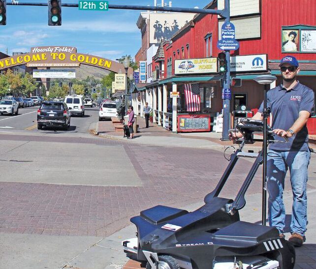
The STREAM EM as a towed array, pictured with GNSS for precise mapping. Credit: BTL.
What GPR returns to the operator can be difficult for the untrained eye to interpret. First-time operators often report that they feel it would be easier to determine the sex of a baby in an ultrasonography image than to interpret GPR. Varied strata look like waves, and hard objects such as pipes appear as parabolas (which are actually hyperbolas, as that is the common term used in GPR verbiage). GPR of this type gets characterized as 2D GPR but can be used as “two and a half D.”
A skilled operator or technician can look at a series of images and essentially “connect the dots” between hyperbolas to try to trace the paths of pipes or other complex structures. The image also gives a depth for the top of the (possible) pipe. A technician may be able to make logical assumptions and draft objects in 3D, but this is time-consuming and highly skilled work. An excellent white paper on the subject is “Utility Mapping Using Multichannel 3D GPR Array Technology” (M. Celaya, A. Novo, M. Sray, K. Tabrizi, and E. Boi).
Spatial inaccuracy of objects identified in separate images, relative to each other, provides a further challenge in this exercise of connecting the dots. Many legacy GPR units have typically relied on wheel encoders and measure- ment tapes solely; the addition of high-precision GNSS, especially RTK or network RTK (RTN), has helped greatly.
GPR Arrays
The application of GPR is still expanding. In addition to utility locating, GPR can be used for archeology, mapping landfills, detecting sinkholes, mapping rebars, concrete scanning, bridge-deck assessment, monitoring bridge scour, highway-related problems, stratigraphic analysis, and many more. It stands as one of the fundamental principles in surveying, photogrammetry, and remote sensing that observations from multiple vantage points can yield 3D positions; of course this would have to be also true of GPR.
From the white paper noted earlier: “An alternative solution to this is creating high-resolution plane view GPR images capable of showing utilities as linear features across the survey area so that a non GPR trained human brain can quickly interpret them. With a transmitter/receiver spacing approaching a 1/4 wavelength of the transmit- ted microwaves into the ground, modular multichannel 3D GPR array systems have greatly improved the speed and areal coverage of the ground together with precise images of the subsurface targets.”
Scientists within IDS GeoRadar (several are co-authors of the paper cited here) capitalized on this very idea of arrays of GPR sensors working in concert. IDS produces GPR array systems consisting of many closely spaced antennas which can be seamlessly integrated with cm-grade positioning devices (GNSS, total stations).
Alexandre Novo, Ph.D., a GPR scientist and geosystems business unit director at IDSNA (IDS North America) further explained: “The STREAM (Subsurface Tomographic Radar Equipment for Assets Mapping) systems were specifically developed for large-scale utility mapping using high-resolution underground imaging. The STREAM systems are composed of modular arrays of a variable number of antennas and frequencies depending on the application and needs.
“The system is scalable because it can drive one to four antenna arrays at the same time. Additionally, the array can be mounted with single or dual polarization. Dual polarization is often useful for mapping utilities buried in two orthogonal directions acquiring data in just one single direction and therefore saving time.”
IDS produce lawn-mower-sized systems like the Opera Duo (dual frequency), and these are suited for simple detection or cursory small-area GPR surveys. Then come their multiple array systems, like the STREAM C: a cart that can be pushed by hand or run on its motorized rear-drive wheels or towed behind a vehicle.
The multiple sensors, 34 on the STREAM C, work in two polarizations to enable 3D definitions. You operate the unit with a ruggedized tablet with the One Vision software. This drives a multi-view screen with GPR radar maps (B-scan and T-scan), radar tomography (C scan), and cartography survey tools. A pipe-detection module automatically identifies individual returns, like on pipes, and connects the dots.
Now, the user can do a survey of a wide area quickly and see a map of candidate pipes, in the field in real-time. Through additional post-processing you can better define the pipes or other features and export those as 3D objects for CAD.
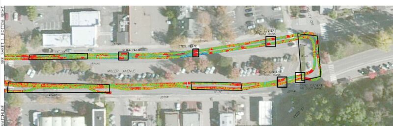
A GPR deliverable from Bess Test-lab; for a roadway improvement project, their client needed to know the precise location of concrete remnants from an older concrete road below.
Integrated Mapping
A step up from the STREAM C is IDS’s STREAM EM. This larger array of 40 sensors in two polarizations is built on a trailer that can be towed at speeds of up to 15km per hour, covering nearly a whole traffic lane in each pass. Real-time high-precision GNSS is typically added to the trailer or prism for tracking with a total station in sky-view challenged areas.
Hexagon (the parent company of Leica Geosystems) purchased the GeoRadar division of IDS in June 2016 and has added other mobile-mapping capabilities to the EM in the form of the Pegasus: Stream. A full Pegasus mobile-mapping system is mounted on the trailer, providing high-speed laser scanning and 360 imaging. The system includes integrated GNNS and inertial positioning. Users can perform 3D above-and-below mapping over wide areas, even whole areas of a city, rapidly, and in a cost-effective manner.
Field Applications
An early adopter of IDS’s multi-array systems is Bess Testlab, Inc. (BTL), a large and established California firm providing a wide array of detection, inspection, and assessment services.
Says Jose Bohorquez, president of BTL, “Our clients are utility companies, cities, counties, municipalities and military installations, contractors, consulting and engineering firms.”
BTL applies multiple technologies to reduce or eliminate uncertainty. Among these are IDS STREAM C, STREAM EM, Opera Duo, and a variety of other detection and potholing systems and surveying and mapping solutions, including UAV. Adds Bohorquez, “We will not leave you with a “wonder.”
Bohorquez, originally from Peru, holds a degree in metallurgical engineering. In 1995, he formed Bess Testlab from an existing lab which he had been a customer of. BTL was born. The company started as a non-destructive testing (NDT) lab: soil borings, concrete cores, sonic technologies, x-rays for testing metal welds and castings. Bohorquez added more metallurgical testing capabilities.
Moving into GPR was a logical progression. Bohorquez said, “We already did x-rays of concrete walls and floors. We knew about GPR and got our first [one] in 1996 and tried it out for a year. We found it was good for deeper in the ground and got a 400MHz antenna so we could do blind search for sewer and storm [pipes].”
“There is a road improvement project [in a city just north of San Francisco] where the client wanted to see how much concrete was under the existing pavement, remnants from an older concrete road,” said Francisco Rojas, project manager at BTL.
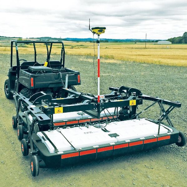
“We pulled the STREAM EM behind an ATV—at street safety speeds of 7 mph—with a [GNSS rover] attached. We did three passes on each lane, with about 10%-20% overlap. Work started about 4:00 a.m. to avoid traffic.”
Rojas explains the tradeoffs between object size, depth, and choice of GPR antenna: “Resolution is basically the smallest target that the GPR can detect. A rule of thumb is that the GPR can detect a target if it is larger than 10% of the wavelength associated with the radar.
“It is not only the size of the target that makes it visible to the radar, but also its depth. The higher-frequency antennas can see shallower depth but with a higher resolution. Lower frequencies can penetrate deeper, but the target size must be at least about 10% of the wavelength of the radar.”
Because some potholing was also performed, this provided BTL with an opportunity to compare the GPR to the results. In all but a few instances, the results for observed utilities matched very well.
Results clearly defined the chunks of concrete remnants. The difference between the concrete and surrounding strata is quite pronounced; GPR keys on the dielectric properties of the mediums, the differences in density. BTL understands that there are some limitations, such as observing in soil with a high clay content or in saturated soil, but still it is rare that they will not find a solution from their extensive toolbox.
I asked Rojas about situations where the sky view for a GPR project is obscured, like tree-lined road rights of way. “We can usually get a [GNSS] fix. But even if we get a bad fix, we can map, like with a [UAV], and align with the map.”
In another project for a major power utility, a two-mile stretch of road needed complete as-built above and below ground. The STREAM EM was towed down the roadway, and the STREAM C was towed along the shoulders and adjacent dirt area. The corridor was then driven with their mobile mapping system.
The above examples highlight the key challenge in dealing with the opaque world of underground infrastructure; we really do not know what is down there. Decades (and in some cases, centuries) of poor documentation of as-built conditions exacerbate the uncertainty.
With multi-sensor GPR, Bohorquez says, “We go from detection to mapping.” Fortunately, for outfits like BTL and the rest of us there are many great options available.
Is it time to give GPR another look?
For more thoughts, check out these articles.
To read the rest of the articles in this print issue, click on the issue cover, below.