In Denmark, a new approach is boosting productivity in maintaining precise vertical data.
EDITOR’S NOTE: Conventional surveying wisdom holds that differential and spirit leveling—and, specifically, digital—are superior to trigonometric leveling. But, with today’s improved instruments, software, and methods (developed over several decades of testing by many parties), results have shown that trig leveling can, if executed with meticulous care, rival these more conventional methods.
This article illustrates why so many surveyors and national geodetic entities have given trig leveling new consideration and have adapted such methods in motorized leveling campaigns: a cost-effective method to level over wide regions or even entire countries.
FOR SUCH A FLAT COUNTRY, Denmark is surprisingly interested in elevations—and for good reason. The low-lying nation is made up of a peninsula and an archipelago of islands surrounded by the Baltic Sea. The country’s mean elevation is roughly 34 m (112 ft), and much of its terrain is flat plains. As a result, Denmark is particularly vulnerable to the effects of rising sea levels.
The concern over elevations is driving an innovative application of geospatial technologies; work is underway to modernize the collection and maintenance of geodetic height information. Having accurate, up-to-date data is crucial, especially in the low areas of the country where rising water levels may impact dams, transportation infrastructure, and agriculture.
Motorized Trig Levels: Improving a Not-so-new Solution
Conventional geometric leveling uses high-precision levels and invar staffs to conduct precise measurements. The approach provides excellent accuracy but is constrained by differences in terrain and limited lengths of sight lines. As a result, geometric leveling is expensive.
Motorized geometric leveling uses vehicles to move instruments and targets quickly along a leveling route. The vehicles simply reduce the time to move from point to point, which helps to reduce the costs.
Trigonometric leveling is a viable—if not widely used—alternative to geometric leveling. With sufficient care, it’s possible to measure longer lines and larger height differences with at least second-order accuracy.
Trig leveling is not a new concept. Soon after the introduction of the first high-precision integrated total stations in the early 1980s, Adam Chrzanowski of the University of New Brunswick demonstrated that trig leveling could produce accuracy of 2mmkm with sight lines as long as 300m and at a speed compatible with conventional geometric leveling. The technique could prove to be especially valuable in hilly or mountainous terrain.
Trig leveling was a featured topic at the 1985 International Symposium on the North American Vertical Datum and again at the 1986 FIG Congress, where a report from the National Land Survey of Sweden also demonstrated good results. And the Swedes added a twist—they used vehicles. It was one of the first demonstrations of motorization for trig leveling.
In a 1989 paper, Chrzanowski provided a detailed description of motorized trig leveling techniques. He used half-second total stations mounted in pick-up trucks and tested leapfrog techniques and reciprocal measurements. He obtained accuracy of between 1mm/km and 2mm/km and concluded that trig leveling could be a logical replacement for conventional geometric leveling.
Chrzanowski found that accuracy of measurement of vertical angles was an important factor in the overall achievable accuracy. Angular accuracy could be improved by taking more observations at each station.
But, he pointed out that to do so using the manually operated total stations available at the time increased observation time to the point that trig leveling would be rendered uneconomical. The experience in Denmark with robotic total stations has removed this concern.
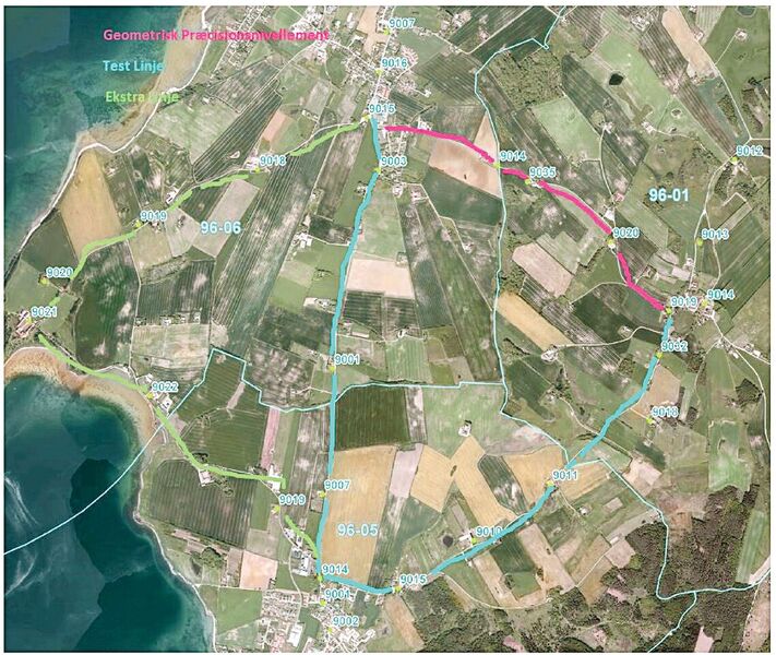
Testing routes for the instruments and software; leveling routes were surveyed twice (blue), and the result was compared to a precise geometric route (red). Another route (green) was used to test the distance meter and prisms.
The work to gather and maintain data on Denmark’s network of vertical control benchmarks falls to the Danish Agency of Data Supply and Efficiency (SDFE).
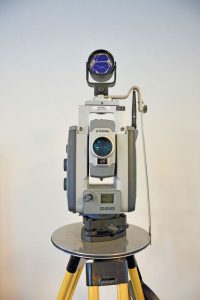
A total station and top-mounted prism assembly for reciprocal measurements. The prism rides in a rotatable bearing to provide stable orientation while the total station turns beneath it.
For years, SDFE has used a combination of conventional geometric and trigonometric leveling to maintain the control points. Recently, the agency began an effort to check bench marks over the entire nation. To meet the technical and budget requirements, surveyors needed to develop an approach that would increase measuring efficiency while preserving precision and accuracy.
The new approach combines motorized trigonometric leveling (MTL) with new total station technology and customized software. The experience gained from work on initial projects has produced encouraging results.
Under MTL, surveying total stations and prism targets are installed in two vehicles and driven from point to point. The vehicles use leapfrog techniques along a route conducting reciprocal measurements that enable analysts to remove systematic error due to refraction and to account for small errors to produce precise vertical differences between the two points. Specially designed mounting systems ensure that the equipment is stable whenever measurements are in progress.
The MTL procedures used by SDFE call for multiple observations in Face 1 and Face 2 positions. The process produces very good accuracy and is much faster than walking and using tripod-mounted instruments and targets. For projects that require second-order precision, motorized trigonometric leveling is an attractive option.
After analyzing the MTL process, geospatial specialists at Geoteam A/S, a Trimble distributor in Copenhagen, realized that much of the field time consisted of physically operating the total station to obtain multiple measurements. They found that by using robotic total stations to make the observations, they could significantly reduce the time needed for the survey.
Using a robotic instrument to perform the sightings instead of manually operated total stations increases the accuracy immediately. An observer’s performance will be affected by weather, distractions, and fatigue, whereas the performance of a robotic instrument is much more stable and is not affected by time, lighting, or environmental conditions.
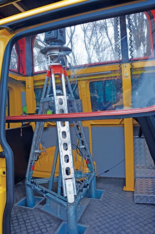
A total station installed in the survey vehicle; custom-built tripods provide stable mounts and the ability to extend and retract as needed.
“The speed of the observations will increase substantially,” said Geoteam director Henrik Johansen. “The time savings in the observation phase should increase the accuracy by minimizing the influence of fluctuating refraction. Alternatively, the saved time could also be used to measure more rounds, which would also increase the accuracy and precision.”
New Designs for Productivity
Working with SDFE, Geoteam specialists developed an approach that would integrate robotic total stations into the SDFE operations. The basics of the solution were formulated to follow strict requirements and were based upon many years of experience.
To meet accuracy specifications, Geoteam used Trimble S9 HP total stations with 0.5” angular precision and robotic operation. The instruments are equipped with Trimble VISION technology, which enables operators to see what the instrument is seeing through its telescope on the laptop controlling the surveys.
Additionally, Geoteam suggested improvements to SDFE’s existing procedures. For example, they suggested mounting a small prism on top of the instruments for tie-in between instrument stations. The concept provided secure position and orientation of the prism for precise measurements. It enables rapid reciprocal measurements between two instrument stations and eliminates the need to remove or reposition prism targets.
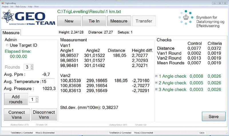
The laptop software collects and displays measurements from both total stations. The solution processes the data and automatically flags observations that don’t meet specifications. Operators can take additional measurements and avoid revisits to correct errors.
SDFE fitted custom-built tripods into the vehicles; the motorized tripods extend through holes in the floor to provide a stable platform for the high-precision total stations. The tripods retract when the vehicles are ready to move to the next observing station.
To conduct operations in the field, Geoteam programmers used the Trimble Precise SDK (software development kit) to create specialized software to run on a laptop in one of the vehicles. Communication between the two survey vehicles is done over a mobile LAN using dedicated routers with a radio backup system.
Additionally, the PCs are connected to the internet to make it possible to use remote desktop software to manage the software and handle operations in both vehicles.
The laptop software controls both instruments to conduct measurements and to store and analyze the data. The software provides measurement options and quality control on the spot to ensure crews meet required accuracy. It controls the functions of the instrument as well as temperature measurements, ppm calculations, averaging the rounds, calculating height differences, accumulated height differences, and accumulated distances.
Operators in the field can inspect the results, remove questionable measurements, or add measurements as needed to meet the defined criteria for precision.

Surveyors can operate the vehicle and measurements from the driver’s seat. Custom software controls both instruments and enables operators to verify results before moving to the next set up.
Test Results
As Geoteam developed the system, they worked with SDFE to conduct a series of tests to better understand the performance and output. In early tests using a 1-second Trimble S8 total station, they measured two known level lines using MTL and compared the results to existing data. The tests produced accuracy of roughly 1mm/km.
Johansen said that subsequent testing using the Trimble S9 HP instruments over a 36-km course showed an error of 0.9 mm/km.
“These results are very impressive,” he said. “Further investigation of temperature measurements, number of rounds, and operational experience indicates that this result can be even better.
The value that the system provides extends beyond its accuracy. Johansen said that the new approach is proving to be very fast. As crews gain experience with the motorized techniques and software, he expects that they will be able to perform precise trig leveling at a rate of two to three kilometers per hour. The savings stem from the faster operation together with the ability to make fewer setups than using conventional levelling over a given route.
At the same time, crew sizes can be cut from four people down to two. Taken together, the changes translate into expected cost savings of 35% compared to current techniques.
The solution also offers advantages in safety and convenience. Operators rarely need to leave their vehicles to work in traffic, and setup locations can be chosen with safety and visibility in mind. Because the instruments are installed in a high position in the vehicle, line of sight is improved, which creates more flexible operation.
The vehicles can be parked in locations not suitable for survey crews working on foot and with standard ground-mounted tripods. The public can travel the roads safely and with little disruption. The higher instrument positions also help mitigate errors due to refraction.
Looking ahead, Geoteam and SDFE also hope that MTL methods can become an adequate substitute for motorized geometric leveling using conventional level instruments—provided that the accuracy reaches the required levels. There are already indications that this is an achievable goal: Johansen said that survey crews using the new solution have delivered accuracy result in the range of 0.6 mm/km.
The efforts of the Danish teams are helping to expand the role of trig leveling. The use of precise total stations driven by well-designed software can transform the work of establishing and maintaining networks of high-accuracy vertical control.
To read the rest of the articles in this print issue, click on the issue cover, below.