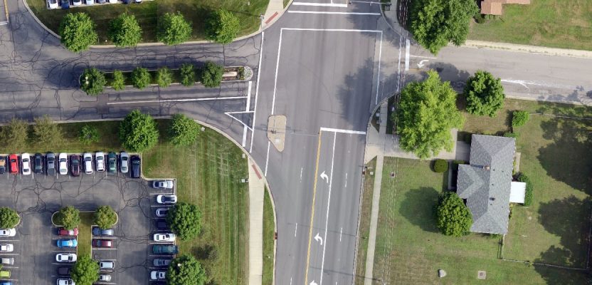
Above: The Inspire 2 drone, using a Zenmuse X7 sensor and 16mm lens, captured this high-resolution image of County Line Road in Beavercreek, Ohio. Credit: Woolpert.
Considering that UAS are just another platform to carry sensors, new mappers should embrace merging photogrammetric techniques and practices with innovations by the computer-vision community to produce scientifically sound mapping products.
The geospatial community is witnessing a golden era of innovation when it comes to sensor technologies, data-processing power, and modeling algorithms. We are taking advantage of a revolution in electronics and integrated circuitry, data-processing techniques and algorithms, sensor manufacturing, and geo-location technologies.
These innovations have positively affected our industry, but they also have resulted in negative implications when it comes to standards of practice. The ease of use of sensors and processing software has made mapping with UAS easy for a nonprofessional. The skills and educational requirements usually required to practice the mapping profession are no longer needed to operate such software at a basic level.
The slow technological evolution of years past offered the right environment for the theoretical and practical aspects of the profession to mature. It also allowed time for professionals to develop best practices for reliable mapping production processes.
Introducing drones to our industry is an example of a fast-moving technological evolution, begging questions like:
- Did this introduction come too quickly?
- Were we unprepared for it?
- Was the use of this technology faster than the pace of our research and development capability could handle?
These are good questions, but they are too often overlooked. What inexperienced people see is that the technology enables them to produce nice-looking maps without huge investments in the needed hardware and software.
Early Drone Mapping
Success at the early stage was mainly driven by affordability, ease of operation, and the many engaging uses of drones. One of these uses includes the bird’s-eye imaging capability that encourages people to purchase a low-cost drone and start acquiring aerial imagery over nearly anywhere.
That wasn’t problematic until some drone operators thought they could go a little further by offering professional mapping services. This leap is due in part to the image-processing software packages on the market that made the task of stitching images and producing attractive mosaics as easy as purchasing a drone.
Such software was designed to streamline the complicated map-making process and enable novice users to produce mapping products, including seamless orthorectified mosaics and digital surface models, regardless of their experience with the map-making process.
Offering the capability of processing UAS-derived imagery is a huge service to the mapping-by-drones community when practiced correctly and professionally. The software allows affordable mapping products to be produced from drone imagery, unlike conventional photogrammetric processing software which would be prohibitively expensive.
Photogrammetry versus SfM
Some traditional photogrammetric software cannot easily handle the excessive sensor-orientation angles that are usually caused by the wind effect on the lightweight body of a small UAS. Most traditional photogrammetric software does not fully utilize the principle of structure from motion (SfM), which is efficient in estimating the geometry of a block of imagery obtained by drones.
The SfM method solves the camera positions and scene geometry simultaneously, using a bundle adjustment of highly redundant measurements based on matching features in multiple overlapping images acquired from different locations. In contrast, the conventional photogrammetric approach requires ideally consistent camera properties and prior knowledge of camera positions or a ground control network.
Although unintentional in some cases, incidents over the last few years reveal clear abuses to map-making standards and practices when it comes to UAS. Many of the UAS-operator-turned-mappers are often excited by the term “SfM,” and some agencies have started calling the team or the unit involved in processing of drone imagery, “The SfM Department.” Some drone-operator-turned-mappers claim that photogrammetric practices and methods are no longer needed when using the SfM approach.
Many of this new generation of mappers neglect the fact that drones are just a new platform that just happens to be unmanned. The imaging process is executed by cameras that are based on the same principle and design of the cameras that have been operated for decades. These cameras are no different than the traditional ones flown on manned aircraft.
Standard practices should still be applied. As a matter of fact, consumer-grade cameras, such as those used on drones, inherit more problems than high-end metric mapping cameras.
Consumer-grade cameras are low-cost, non-metric cameras with low-quality lenses and shutters. The global positioning system (GPS) used with these cameras is frequently based on the less-accurate, single-frequency receiver. Performing camera calibration and modeling GPS timing and positioning error techniques were perfected by the photogrammetric community over the last few decades.
Moreover, bundle block adjustment, least squares, and adjusting products to fit datum and coordinates systems were not the inventions of the SfM scientists. These are the results of decades of hard work by the extensive community of geodesists, photogrammetrists, and mapping scientists.
Software based on SfM principles is great for constructing a 3D scene and producing a 3D product, but without borrowing some photogrammetric principles in camera self-calibration, geo-located bundle block adjustment, least squares errors distribution, and modeling of GPS/inertial measurement unit (IMU) shift and drift, the derived products will be anything but positionally accurate.
Proper Knowledge Needed
I plead to the new community of mappers to embrace the new reality of merging photogrammetric techniques and practices with innovations by the computer-vision community to produce scientifically sound mapping products. Relying on push-button, black-box-based processing alone is a risky undertaking, since the mapping process and imaging sensors are complicated. Users eventually will run into situations where only proper knowledge of photogrammetric and mapping principles will be able to produce a quality product.
The mapping community offers tremendous opportunities for these new mapping practitioners through many American Society of Photogrammetry and Remote Sensing (ASPRS) workshops and certifications. Several schools around the country also offer good online classes on geospatial and photogrammetric sciences.
To be able to build accurate mapping product lines from drones, you need more than the drone pilot license. Drone pilots should reach out to the greater community of mappers and surveyors to help you navigate through this complex yet fascinating world of map-making.
Accuracy
With that said, let us dig into the reality of whether these low-cost cameras can produce accurate mapping products. Several publications present conflicting conclusions on the accuracy of products derived from UAS, some of which present ridiculously unrealistic and exaggerated claims.
In my opinion, and based on the results of my own research, products derived from UAS can be accurate if and only if users understand the conditions that result in accurate bundle block adjustment. Anyone can produce a nice-looking map using the SfM-based software because they are known for ease of use. However, not everyone can produce an attractive and accurate map that a licensed professional would endorse.
To get an accurate map, you need to satisfy basic criteria, including:
The imagery must be acquired at the highest quality possible to satisfy the following conditions:
• taken during good light and weather conditions;
• free from shadow or cloud shadow as much as possible;
• not taken with an overly wide-angle lens, such as a fish-eye lens (wider lens is characterized by increased lens distortion resulting in degraded image quality);
• taken with a camera with a global shutter to minimize the image blurring effect (rolling shutters tend to degrade image quality);
• flown with 80% forward lap and 60% to 70% side lap. Such high overlap is necessary to increase the reliability figures in the photogrammetric solution while providing optimum condition for multi-rays’ photogrammetry.
A minimum of five to nine ground control points should be well distributed across the project area and are surveyed to the required accuracy.
The processing software should be capable of modeling and correcting camera internal parameters and GPS/IMU anomalies or errors.
Operators should use a UAS with a dual frequency receiver and post-process kinematic capability.
Four Success Factors
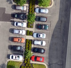
Figure 1: High-resolution imagery from a UAS with a resolution of 2.0 cm.
Low-altitude and high-resolution imagery
Low-altitude imaging not only results in high-resolution imagery (Figure 1), but it also minimizes the effect of the altitude errors on the derived products. After the aerial triangulation solution, there will always be residual errors in the computed camera attitudes angles.
The effect of such errors on the derived products is linearly proportional to the flying altitude, as illustrated in Figure 2 and the following equations:
∆Y = H · tan ∆ (1)
∆Y = H · tan ∆ (2) where,
∆ = Omega error
∆ = Phi error
∆Y = Position error caused by error in Omega
∆X = Position error caused by error in Phi
H = Flying altitude.
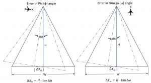
Figure 2: First order estimation of ground error from aerial photogrammetry.
As Equations 1 and 2 demonstrate, the higher we fly the sensor, the more errors are introduced in the positions of the derived products. Figure 2 illustrates the influence of flying altitude on the estimated products’ accuracy derived from photogrammetry or lidar. With manned aircraft, we usually fly around 3000 feet to 10,000 feet above ground level, while most of UAS missions are conducted from an altitude of 70 feet to 200 feet. Such low-altitude results in lower positional errors caused by the errors in sensor orientation angles determination from aerial triangulation.
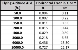
To illustrate the impact of flying altitude on resulting accuracy, Table 1 lists the estimated horizontal positional errors caused by an error of 15 arc seconds in omega and phi during the aerial triangulation process (as computed using Equations 1 and 2). Such remaining error in the camera orientation determination is expected, and the value of 15 arc seconds is realistic even for high-quality aerial triangulation adjustment. Table 1 clearly shows that those positional errors remain low for UAS flights (i.e. flown under 400 feet) but are much higher for typical imaging missions using manned aircraft.
Small project size
The smaller size of projects associated with UAS acquisition helps minimize the error sources in the bundle block adjustment and eventually results in a better management for the error modeling during adjustment.
In addition, smaller project size translates to fewer number of images and therefore a better ratio of images to ground control points, assuming ground control points are used in the block adjustment. Image redundancy
UAS-based imagery is usually flown with excessive forward and side overlap. Such increased overlap results in increased “reliability figure,” an important measure for estimating the quality and the fidelity of the photogrammetric solution. Figure 3 illustrates a ground control point that appeared in 40 images in a project whose flight plan is illustrated at the left side of the figure.
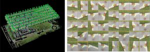
Figure 3: Left: Flight plan of the project. Right: 40 images of one ground control point from aerial photogrammetry.
In addition to strengthening the reliability figure in the solution, image redundancy provides the right environment for processing software that utilizes the concept of multi-ray photogrammetry, which results in a better aerial triangulation solution and better products.
Processing software and matching algorithms
Software such as Pix4D, Metashape (formerly Photo- scan), and SimActive COR- RELATOR3D should share the credit for the fast integration of drones by the mapping industry. Some of these software packages utilize the SfM approach to resolve drone imagery geometry. Some utilize highly advanced matching algorithms, such as Scale-Invariant Feature Transform, Speeded-Up Robust Features, and SemiGlobal Matching, which result in the highest quality tie/pass points for aerial triangulation and surface models.
Figure 4 illustrates the sheer number of tie/pass points generated for one UAS-based image. This density of tie/pass points, with an average of 1000 to 2000 points per image, is unprecedented, as conventional photogrammetric practices result in only up to nine tie/pass points per image (or six Von Gruber points per stereo model).
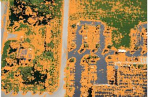
Figure 4: Distribution of matched tie/pass points (represented as orange + symbols) in a drone image.
Having such high number of tie/pass points contributes to a high-fidelity bundle block solution. Figure 5 illustrates the high quality of digital surface model generated by these new matching algorithms.
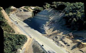
Figure 5: High-quality point clouds from consumer-grade camera imagery.
Advanced error modeling capabilities
Most processing software used for UAS-based imagery employs sophisticated error modeling algorithms to compensate for the shortcomings of the consumer-grade cameras and the low-cost GPS and IMU devices. Performing camera self-calibration during the bundle block adjustment solution is crucial to the success of any UAS mapping mission.
Modeling errors in sensor position due to the low-grade GPS receivers used with many low-cost UAS is no less important than the camera self-calibration process. Camera self-calibration is a well-known technique developed during the last few decades within the photogrammetric community and is adopted by the new UAS image-processing software. Developers of these new software need to adopt the techniques developed by the photogrammetric community to model GPS and IMU shifts and drifts.
UAS and ASPRS Mapping Standards
Many times I am faced with the question of whether I should accept mapping products from UAS. My answer is yes, as long as you consider the following common-sense practices:
1) Make sure that the data provider follows a stringent photogrammetric workflow and is aware of the four criteria listed above for producing accurate mapping products.
2) Always remember that the derived product will never be as or more accurate than the ground control points used in the photogrammetric process to generate the product.
3) Demand that the products meet an industry mapping accuracy standard. For this, I suggest specifying the new “ASPRS Positional Accuracy Standards for Digital Geospatial Data” in the contract. This is the only standard designed for digital geospatial data. The new ASPRS mapping accuracy standards simplify the process while providing legal protection in case the data producer fails to meet the data quality requirements specified in the contract.
Once you specify the accuracy for the final products in the contract, the new standards set the required accuracies that need to be achieved during the various phases of product generation. For example, the standards set the required accuracy for the ground control points and the accuracy of aerial triangulation without specifying it in the contract (Figure 6).
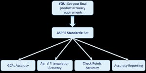
Figure 6: The new ASPRS standards and products accuracy criteria.
The standards also specify the accuracy of the check points to be used to verify the delivered product accuracy and will dictate a formal accuracy statement to be provided by the data provider.
False Accuracy Claims
Although some of the drone-based product providers advocate the new ASPRS standards when marketing their products, they pay little attention to the meaning of product accuracy as specified by the ASPRS standards. Frequently they claim their products are produced to meet an accuracy of 1 cm or better. This claim is problematic for the following reasons:
Wrong approach for accuracy evaluation
Product accuracy according to ASPRS standards must satisfy the following conditions:
1) Accuracy should be assessed by using a set of independent-surveyed (or derived from other sources) ground check points that are more accurate than the tested products. Independent check points are ground control points that are not used in the aerial triangulation for that project.
2) For a valid statistical sample, there should be at least 20 check points used in the accuracy assessment regardless of the project size.
3) Check points should be at least three times more accurate than the tested product.
Besides violating the ASPRS standards conditions on accuracy evaluation, many of those providers report the results of the ground control fit in aerial triangulation to express their products accuracy. This is the wrong approach as the aerial triangulation subjects the ground control points to a stringent constraint, which disqualifies it as an independent check point.
For Planimetric Mapping Products
According to the new ASPRS positional accuracy standards, for an orthorectified image or planimetric vector mapping product to be produced to meet a horizontal accuracy of 1 cm, the following conditions need to be satisfied:
1) The ground control used for the aerial triangulation process needs to be surveyed to a horizontal accuracy of 0.25 cm as Root Mean Square Error (RMSE) and vertical accuracy of 0.50 cm as RMSE.
2) The accuracy of the aerial triangulation needs to be within 0.50 cm as RMSE horizontally and 1.0 cm vertically as RMSE.
For Topographic Mapping Products
According to the new ASPRS positional accuracy standards, for a digital surface model or digital terrain model to be produced to meet a vertical accuracy class of 1 cm, the following conditions needs to be satisfied:
1) The ground control used for the aerial triangulation process needs to be surveyed to a horizontal accuracy of 0.25 cm as RMSE and vertical accuracy of 0.25 cm as RMSE.
2) The accuracy of the aerial triangulation needs to be within 0.50 cm as RMSE horizontally and 0.50 cm vertically as RMSE.
Looking at the stringent horizontal and vertical accuracy requirements for the ground control survey of 0.25 cm, an experienced mapper can see that real-time kinematic-GPS field surveying practices cannot be utilized for this type of survey work and that costly differential levelling is the only method that can achieve such accuracy. The high cost of this highly accurate ground control survey is prohibitively expensive and not suitable for low-cost UAS-based products.
The new UAS-based mappers need to understand that most of the field survey work conducted to support aerial mapping usually meets an accuracy of 2 cm (as RMSE) unless otherwise requested. Ground control points surveyed to an accuracy of 2 cm are only useful to produce mapping products that are accurate to 8 cm according to ASPRS standards and it does not support the 1-cm accuracy claim that many UAS-based mappers advocate.
Collaboration and Certification
Finally, our success in using UAS for mapping product generation can be credited to the past achievements within the photogrammetric community and the introduction of several innovative approaches by the non-mapping community. This collaboration between the two communities has resulted in an extremely efficient workflow for processing UAS products. Without this cooperation, the use of UAS for mapping would not be as prevalent as it is today.
My advice for the UAS-operators-turned-mappers community is to understand that UAS is just another platform to carry aerial cameras and other sensors. The mapping community has developed techniques and processes to deal with imagery over the last century. I advise these UAS operators to join the larger mapping community through participation, open dialogue, and seeking professional mapping certification.
Among its professional certifications, ASPRS offers two programs that are dedicated to professionals who specialize in one or more of the following UAS activities:
1) design, operation, and management of survey, mapping, and remote sensing projects using UAS;
2) analytical techniques and methods for processing UAS-acquired data;
3) UAS system design and research;
4) performing or supervising routine tasks to collect, process, and interpret data acquired with UAS for use in surveying, mapping and remote sensing applications.
In addition, I hope that members of the mapping community will embrace the presence of the new UAS operators-turned-mappers among us and support them by sharing their knowledge, fostering their education and giving advice. Working together will only enrich our geospatial mapping community, make us stronger professionals, and produce the best mapping products to benefit everyone.
The original version of this article appeared in the May issue of the journal PE&RS.